Leak detection in roof membranes

a leak detection and roof membrane technology, applied in the direction of fluid leakage detection, fluid tightness measurement, instruments, etc., can solve the problems of premature roof failure, inability to detect, find and correct, and costly roofing problems, so as to reduce the voltage of the measurement circuit, inhibit corrosion and electrolysis, and enhance the operation of the guard conductor

Active Publication Date: 2017-07-04
DETEC SYST
View PDF7 Cites 12 Cited by
  • Summary
  • Abstract
  • Description
  • Claims
  • Application Information

AI Technical Summary

Benefits of technology

[0039]To enhance the operation of the guard conductors which are driven from the same supply that is used for the sensor conductor measurement circuit, the voltage to the measurement circuit can be reduced by a volt more thus making the guard circuit more attractive to stray currents outside of the grid zone that is currently being measured.
[0040]The same guard conductors can also be used for a cathodic protection system in which a secondary cathodic protection supply and switch is provided such that in the off state, when no measurements are being made, a low voltage (usually about −0.85 to −1.1 Vdc), cathodic protection supply is applied between all the X and Y guard conductors and the building ground connected to the rood deck to inhibit corrosion and electrolysis.
[0041]If needed, a permanent guard wire can be place around conductive roof penetrations to provide further isolation and avoid false readings.

Problems solved by technology

The failure to detect, find and correct minor roof deterioration in the earliest stages is considered the greatest cause of premature roof failure.
Costly roofing problems are often the result of design deficiencies or faulty application of the roof system.
Even when properly designed and applied, all roofing materials deteriorate from exposure to the weather at rates determined largely by the kind of material and the conditions of exposure.
This is becomes a particular problem for inverted roof assembly membranes (IRMA) roofs where the roof membrane is typically bonded to a concrete deck and any leak detection system needs to be located on top of the membrane which is usually covered with a thin layer of water.
The vector mapping method it limited in its ability to locate the ground fault signal when the IRMA roof includes insulation and heavy overburden such as a vegetative covering.
However, where there are two breaches including a first breach close to an x grid location only and a second breach at a location next to a y grid location only can, the analysis of the voltages can result in an incorrect assessment that there is a single breach in the grid sections where the x and y wires of the grid intersect.

Method used


Image

  • Leak detection in roof membranes
  • Leak detection in roof membranes
  • Leak detection in roof membranes

Examples


Embodiment Construction

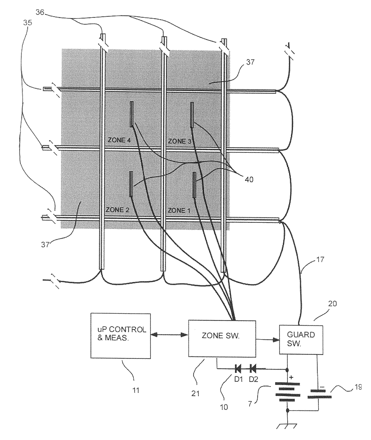
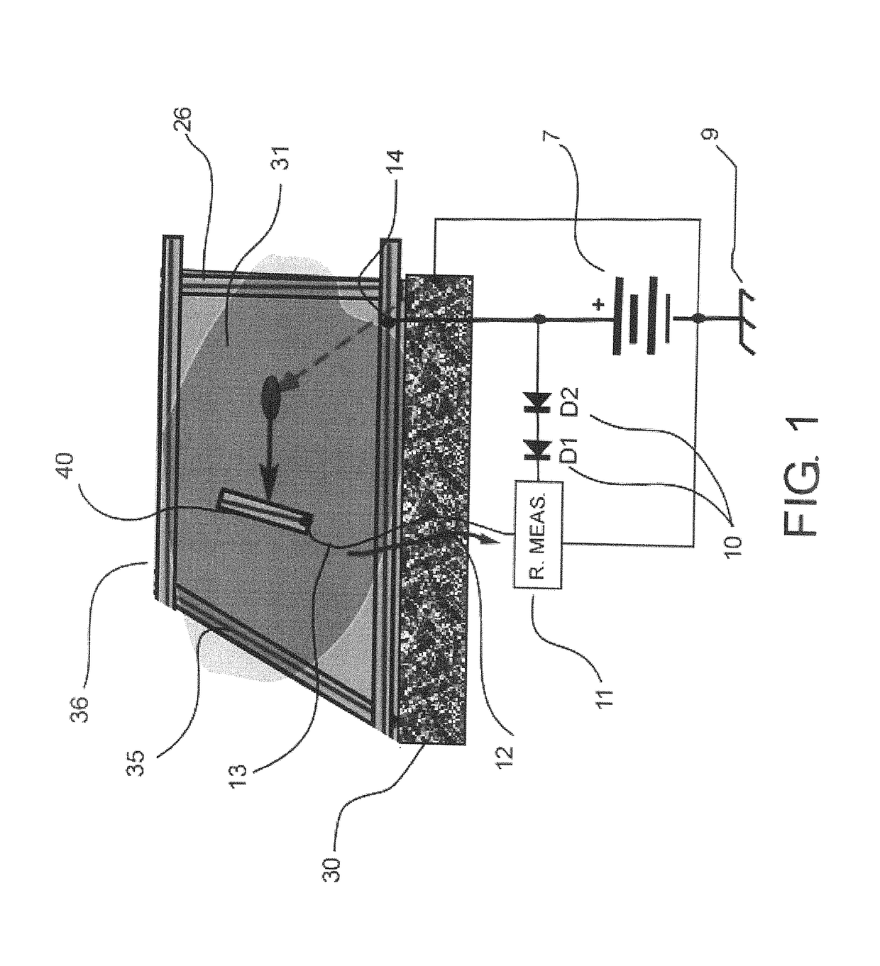
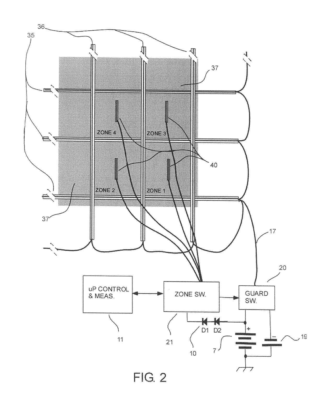
[0050]Referring now to the drawings, the overall arrangement of the subject roof membrane moisture detection system can best be seen with reference to FIGS. 1 and 2. A roof membrane 31 is illustrated which is applied as a direct covering layer over a roof deck 30. The deck is typically of concrete but can be of any suitable material that is sufficiently conductive to allow the detection of a low level electrical current travelling through the deck to a measurement ground. The membrane is a water impervious material such as thermoplastics and is sealed at any joints to provide a continuous water barrier over the roof deck. This barrier is intended to provide the leak prevention and any penetration therein caused by a puncture or faulty seal or by wear can allow the moisture to penetrate to the deck where it can cause damage or can continue into the structure to cause damage to internal structures. The membrane is typically covered by a drainage layer 2, thermal insulation 3 and a sur...


PUM

PropertyMeasurementUnit
electrically conductiveaaaaaaaaaa
electrical potentialaaaaaaaaaa
currentaaaaaaaaaa

Abstract

Leaks in a roof membrane are detected by applying a grid of electrically conductive shielding elements on the upper surface separating the membrane into a plurality of zones and generating a potential difference between the elements and a conductive component such as the roof deck or a layer at the deck. In each zone a respective one of a plurality of sensor conductors is mounted separate from the shielding elements and an electrical potential difference is applied between the sensor and the conductive component such that, in the presence of a leak located within the zone, current flows between the sensor conductor and the conductive component through moisture at the leak for detection of the current or resistance indicative of a leak.

Description

[0001]The present invention relates to a system for monitoring roof membranes for the presence and location of moisture penetration. It has particular application to monitoring low-slope and flat roofs of residential and commercial buildings for undesired water ingress.BACKGROUND OF THE INVENTION[0002]The failure to detect, find and correct minor roof deterioration in the earliest stages is considered the greatest cause of premature roof failure. This is particularly true of roofing materials applied on low-slope or flat roofs. Costly roofing problems are often the result of design deficiencies or faulty application of the roof system. Even when properly designed and applied, all roofing materials deteriorate from exposure to the weather at rates determined largely by the kind of material and the conditions of exposure.[0003]Several methods have been used to try and locate roof leaks after they have occurred. This is becomes a particular problem for inverted roof assembly membranes ...

Claims


Application Information

Patent Timeline
Patent Type & Authority Patents(United States)
IPC IPC(8): G01N27/04G01M3/16E04D13/00
CPCE04D13/006G01M3/165G01N27/048
Inventor VOKEY, DAVID E.BRIDGES, MARK K.
Owner DETEC SYST
Why Eureka
Try Eureka