Radiation generating tube and radiation generating apparatus including radiation generation tube

a radiation generating apparatus and radiation generating tube technology, which is applied in the direction of radiation diagnostic diaphragms, applications, and handling using diaphragms/collimeters, etc., can solve the problems of increasing the volume of the radiation generating member, the conversion efficiency of radiation generation efficiency is low, and the weight and size of the radiation generating apparatus is increased

Active Publication Date: 2017-07-04
CANON KK
View PDF16 Cites 18 Cited by
  • Summary
  • Abstract
  • Description
  • Claims
  • Application Information

AI Technical Summary

Problems solved by technology

The “radiation generation efficiency” means a radiation output intensity to kinetic energy of incident electrons, and a low conversion efficiency of the radiation generation efficiency has been a problem in size reduction and weight reduction.
The shielding member is disposed to surround a radiation source, and therefore it increases the volume of the radiation generating member, which in turn increases the weight and size of the radiation generating apparatus.
In such a radiation generating apparatus, radiation emission to areas other than a predetermined observation field is not useful, and the variable opening type collimator is used to limit the amount of unnecessary exposure to the specimen or subject.

Method used


Image

  • Radiation generating tube and radiation generating apparatus including radiation generation tube
  • Radiation generating tube and radiation generating apparatus including radiation generation tube
  • Radiation generating tube and radiation generating apparatus including radiation generation tube

Examples


Embodiment Construction

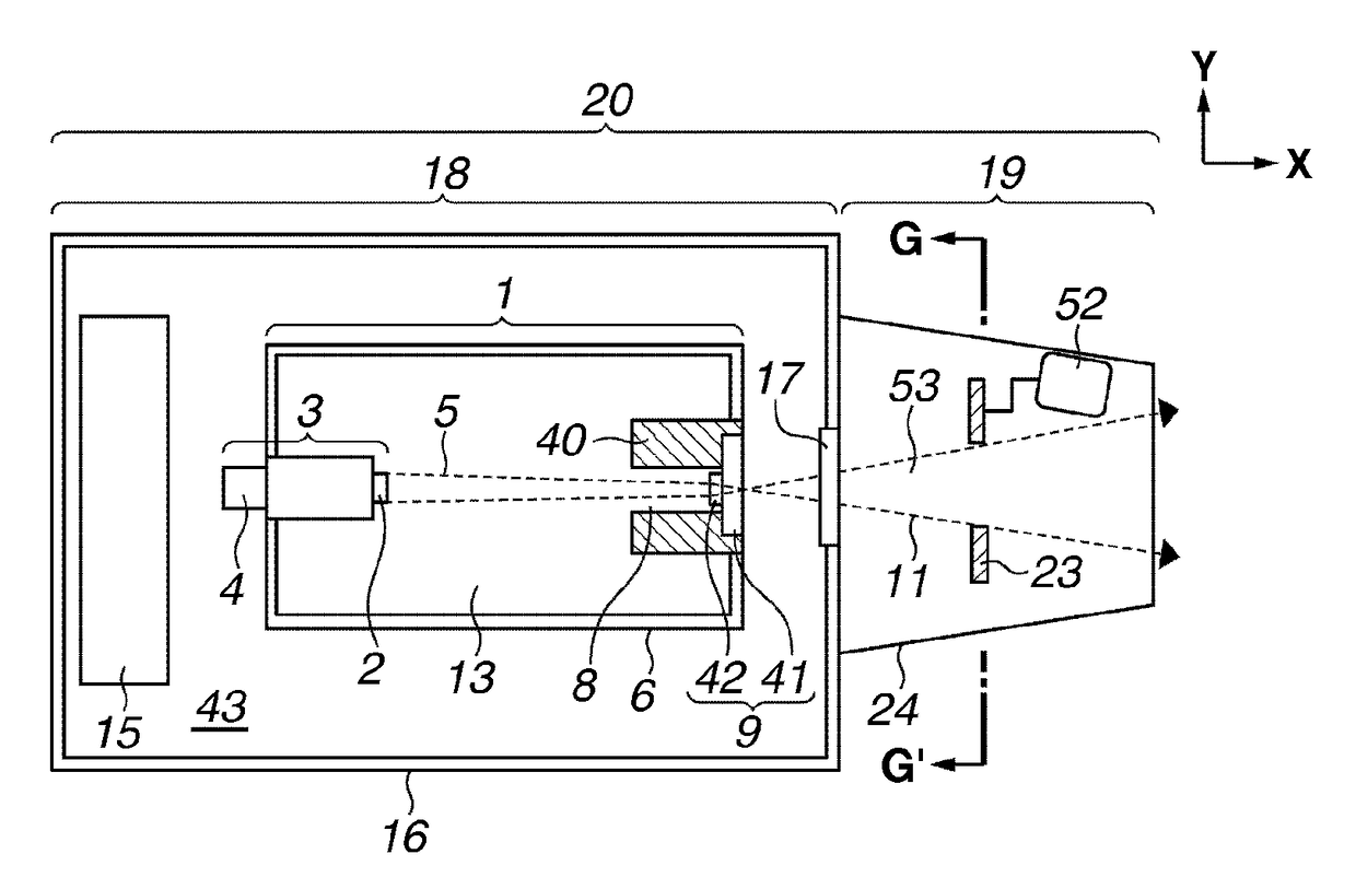
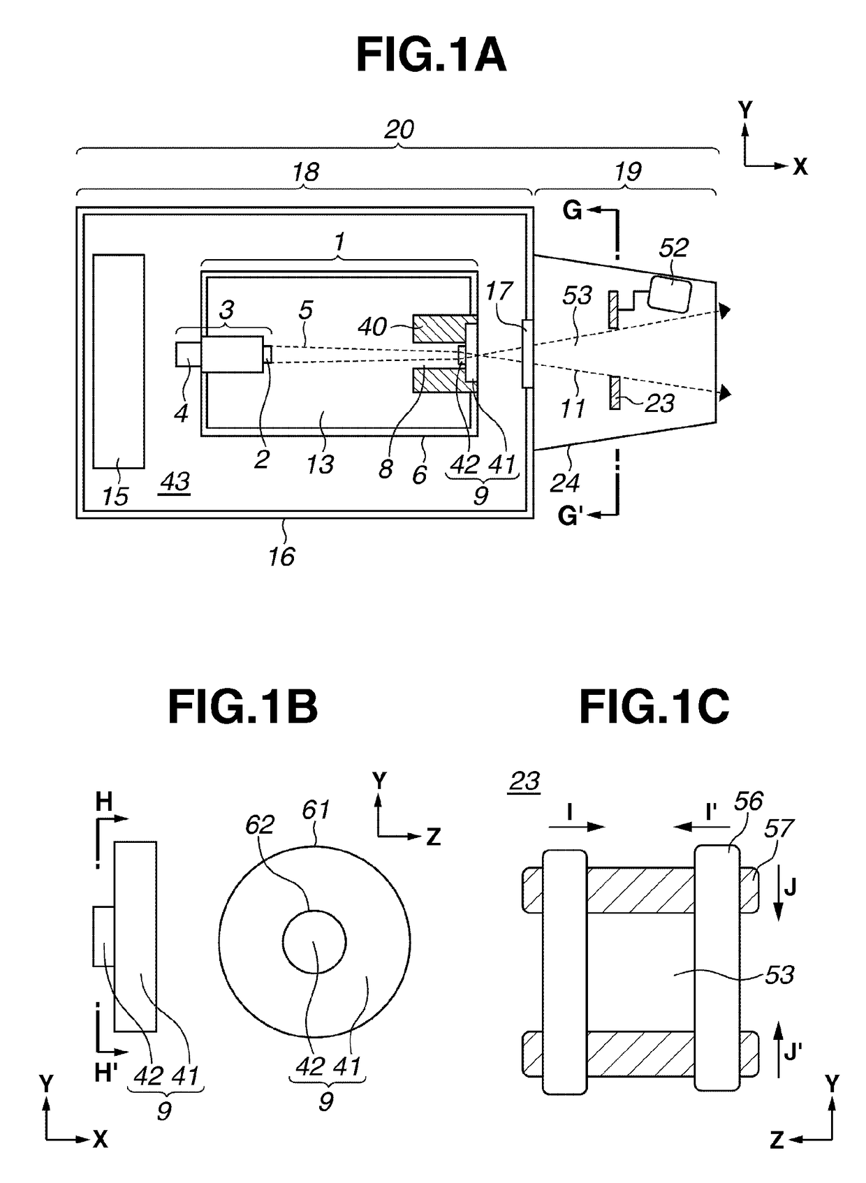
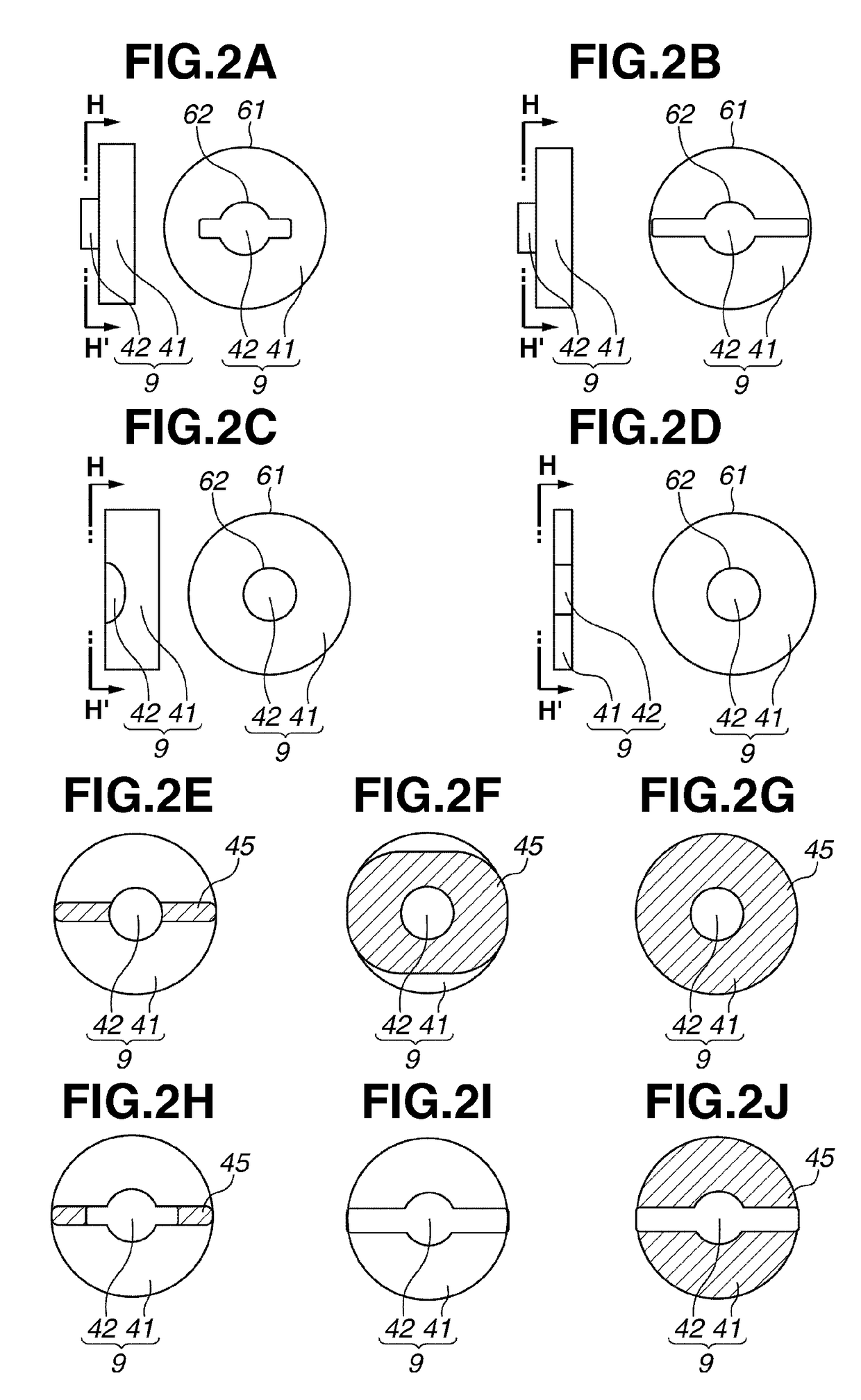
[0041]With reference to FIGS. 1A to 1C, a basic structure of a radiation generating apparatus according to an exemplary embodiment of the present invention will be described. FIG. 1A is an overall view illustrating a radiation generating apparatus according to the present exemplary embodiment. Further, FIG. 1B illustrates a structure of a target applicable to the radiation generating apparatus according to the present exemplary embodiment. Further, FIG. 1C illustrates a collimator applicable to the radiation generating apparatus according to the present exemplary embodiment.

[0042]In present exemplary embodiment, a radiation generating apparatus 20 includes a radiation generation unit 18 having a radiation generation tube 1, and an objective unit 19 having a collimator 23.

[0043]With reference to FIG. 1A, the radiation generation unit 18 according to the present exemplary embodiment is described. The radiation generation unit 18 according to the present exemplary embodiment includes t...


PUM


Abstract

A radiation generating apparatus includes a radiation generation tube including an electron emitting source having an electron emitting member, a transmission type target, a tubular backward shielding member having an electron passing hole facing the target layer at one end, located at the electron emitting source side of the transmission type target, and connected to the periphery of the base member. The radiation generating apparatus further includes a collimator having an opening for defining an angle for extracting the radiation at the opposite side of the electron emitting source side of the transmission type target, and an adjusting device connected to the collimator, and configured to vary an opening diameter of the opening, wherein the target layer has a portion separated from a connection portion of the base member and the backward shielding member at the periphery.

Description

BACKGROUND OF THE INVENTION[0001]Field of the Invention[0002]The present invention relates to a radiation generating tube, and a radiation generating apparatus including the radiation generating tube.[0003]Description of the Related Art[0004]Needs for small and lightweight medical modality with portability have been increasing with changing of social conditions such as improvement in the home medical care system and expansion of the range of treatment in emergency medical system. To respond to these needs, with developing of analysis diagnostic techniques in the medical field, various medical modalities have been developed. Radiation imaging apparatuses having a radiation source are, due to the sizes of the apparatuses, mainly fixed and installed in hospitals and medical testing facilities. Such radiation generating apparatuses having the radiation source are also required to be reduced in size and weight to use them as modalities applicable to home medical care and emergency medica...

Claims


Application Information

Patent Timeline
Patent Type & Authority Patents(United States)
IPC IPC(8): H01J35/16A61B6/06A61B6/00A61B6/08G21K1/02
CPCH01J35/16A61B6/06A61B6/40A61B6/08G21K1/02H01J2235/081H01J2235/086H01J2235/087H01J2235/168H01J35/116
Inventor OGURA, TAKAONOMURA, ICHIROUEDA, KAZUYUKISHIOZAWA, TAKASHI
Owner CANON KK
Why Eureka
Try Eureka