Directional tissue expander

a tissue expander and expansion tube technology, applied in the field of expansion implants, can solve the problems of reducing the safety margin of the device, causing the expansion of the expander to expand in undesired directions, and overinflating the expander to be undesirabl

Active Publication Date: 2017-07-11
MENTOR WORLDWIDE
View PDF32 Cites 8 Cited by
  • Summary
  • Abstract
  • Description
  • Claims
  • Application Information

AI Technical Summary

Problems solved by technology

With known mammary tissue expanders, as the inflation process continues, resistive pressure from the tissue on the anterior side of the expander can cause the expander to expand in undesired directions (i.e., axially and laterally).
Overinflating a smaller expander is undesirable for various reasons.
Although expanders are technically tested up to twice their nominal inflation volume, 200-300% inflation could reduce the safety margin of the device.
Further, since the footprint is small, at 200-300% inflation the inflated shape is not anatomically correct, but rather is more round or ball-like, which could lead to rotation or flipping over of the implant within the tissue pocket.

Method used


Image

  • Directional tissue expander
  • Directional tissue expander
  • Directional tissue expander

Examples


Embodiment Construction

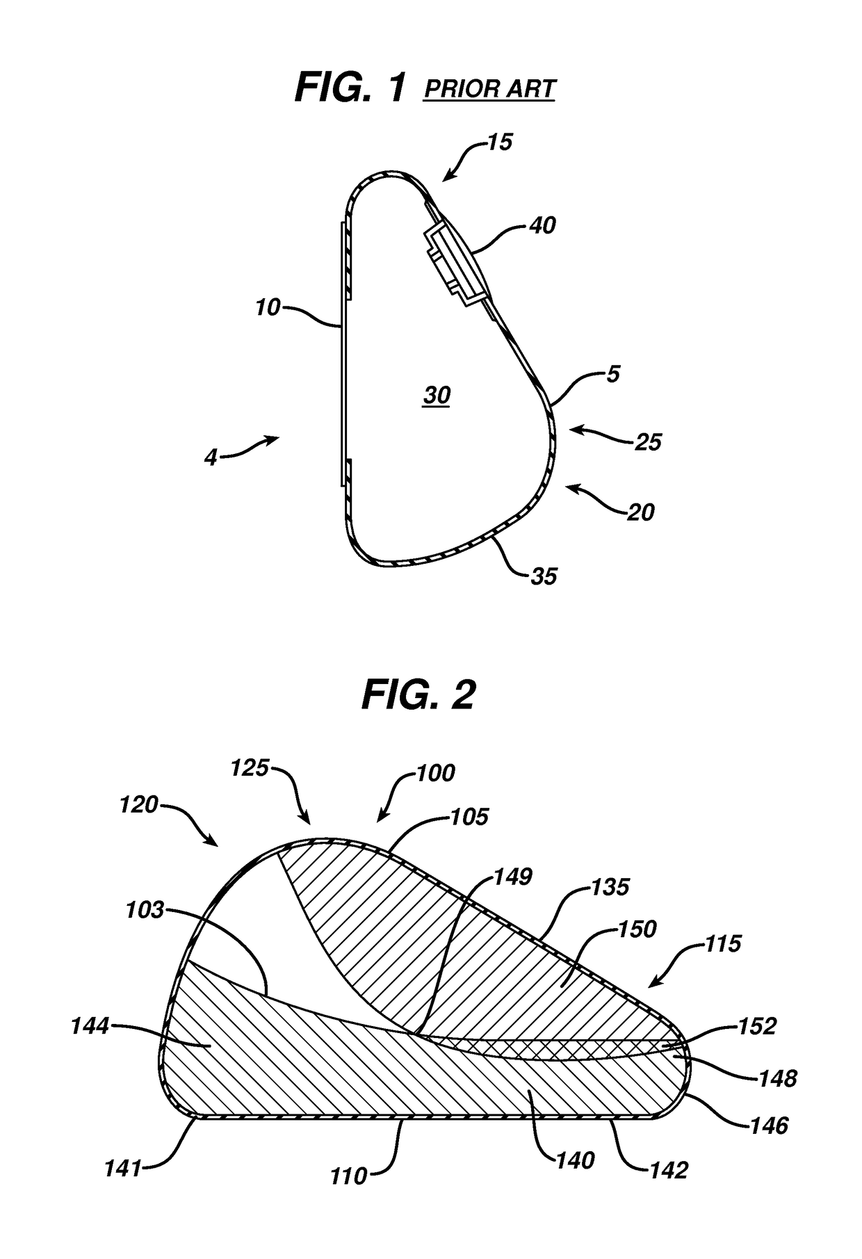
[0031]FIG. 1 shows a cross-sectional side view of an exemplary prior art mammary tissue expander 4. The expander has a posterior face 10 that lies substantially flat and is placed against a patient's chest wall, and an anterior face 5 that faces outward from the chest wall when implanted. The anterior face 5 includes an upper pole region 15 (i.e., the upper portion of the shell when the implant recipient is standing), a lower pole region 20 (i.e., the lower portion of the shell when the implant recipient is standing), and an apex 25 (corresponding to the point at which the nipple would be in a natural breast) separating the upper pole region and the lower pole region. The outer shell 35 of the expander 5 is typically made of a silicone material and includes an injection port or other valve or self-sealing zone 40 through which saline or another fluid is injected over time into the contained inner region 30. In this manner, the volume of the expander can be increased over time until ...


PUM


Abstract

An expandable mammary implant including a shell having an anterior face and a posterior face. The anterior has an upper pole portion and a lower pole portion meeting at an apex, and an injection zone for receiving fluid therethrough to inflate the implant. A reinforcement material is coupled to the shell in a reinforcement zone. The reinforcement material is coupled to the shell so as to at least coincide with the upper pole portion and a peripheral rim portion that extends from the posterior face upwardly into said anterior face by a predetermined distance.

Description

FIELD OF THE INVENTION[0001]The present invention relates generally to the field of expandable implants, and more particularly to expandable mammary implants.BACKGROUND[0002]Tissue expanders are devices that are implanted beneath the skin and then gradually inflated to stretch the overlying tissue. Such expanders are used to create a pocket for receiving a permanent prosthesis and / or to generate increased skin surface area so that skin can be utilized for grafting or reconstruction.[0003]In the case of mammary implants, tissue expanders are used to create the mammary pocket that will ultimately receive the permanent mammary implant. These expanders are commonly formed of a silicone polymer shell. After implantation, saline or some other fluid is periodically injected into the expander over time, for example through an injection port, until the desired sized pocket is achieved.[0004]With known mammary tissue expanders, as the inflation process continues, resistive pressure from the t...

Claims


Application Information

Patent Timeline
Patent Type & Authority Patents(United States)
IPC IPC(8): A61F2/12
CPCA61F2/12A61F2250/0003A61F2250/0018A61B90/02
Inventor DAVILA, LUIS ALBERTOFALCON, ANITA M.HRISTOV, KRASIMIRAKRIKSUNOV, LEO B.TANNHAUSER, ROBERT J.
Owner MENTOR WORLDWIDE
Why Eureka
Try Eureka