
Method and system for exhaust catalyst warming

a technology of catalyst and exhaust, applied in the direction of electric control, ignition automatic control, machines/engines, etc., can solve the problems of limiting the amount of spark retard and air flow that can be obtained, engine combustion may become unstable, and undesirable nvh effects

Active Publication Date: 2017-07-18
FORD GLOBAL TECH LLC
View PDF12 Cites 12 Cited by
  • Summary
  • Abstract
  • Description
  • Claims
  • Application Information

AI Technical Summary

Benefits of technology

This approach enables faster catalyst heating with improved NVH characteristics and reduced emissions during engine cold-starts by adjusting cylinder deactivation patterns and engine speed based on temperature and load conditions.

Problems solved by technology

However the inventors herein have recognized that there may be limitations to the amount of spark retard and air flow that can be obtained.
For example, if the spark timing is overly retarded, engine combustion may become unstable.
As such, this may lead to undesirable NVH effects.

Method used


Image

  • Method and system for exhaust catalyst warming
  • Method and system for exhaust catalyst warming
  • Method and system for exhaust catalyst warming

Examples


Embodiment Construction

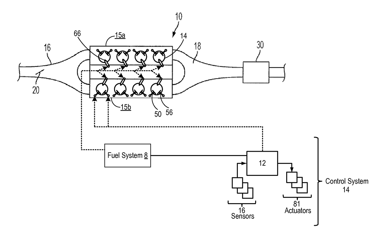
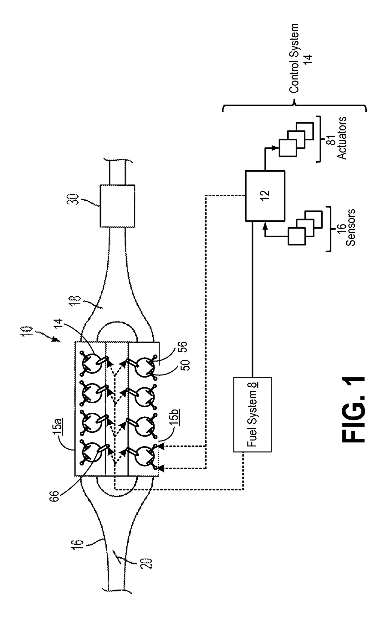
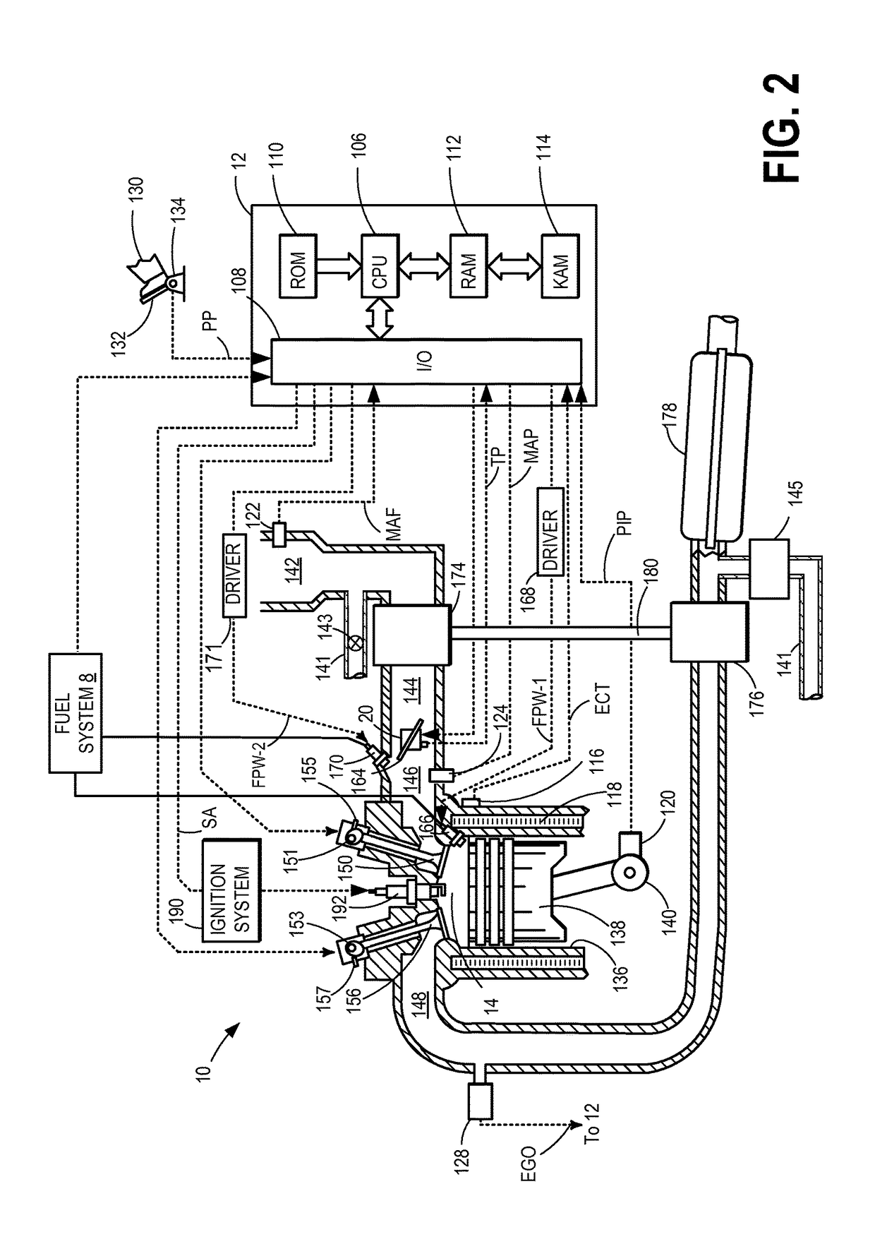
[0016]Operating an engine with skip fire, where at least one cylinder of the engine is skipped and not fired during each engine cycle, may improve fuel economy and emissions during certain operating conditions, such as low engine load. An engine configured to operate with skip fire is illustrated in FIGS. 1-2, and FIGS. 3-4 illustrate cylinder firing plots for the engine of FIGS. 1-2 in a non-skip fire mode (FIG. 3) and in a skip fire mode (FIG. 4). An engine controller may be configured to perform a control routine, such as the example routine of FIG. 5, to adjust an engine speed while operating the engine in a skip-fire mode during an engine cold-start. This allows the heat flux to the engine to be increased, expediting exhaust catalyst activation. An example operation is shown with reference to FIG. 6.

[0017]FIG. 1 shows an example engine 10 having a first bank 15a and a second bank 15b . In the depicted example, engine 10 is a V8 engine with the first and second banks each having...


PUM


Abstract

Methods and systems are provided for leveraging engine skip-fire operation during an engine cold-start to expedite catalyst heating. Based on the heat flux required, the engine may be operated with a group of cylinders selectively deactivated, with spark retard on remaining active cylinders increased, and with engine speed increased to reduce NVH issues during the skip-fire operation. The combination of parameters may be adjusted based on changes in exhaust temperature and NVH limits of the engine.

Description

FIELD[0001]The present application relates to methods and systems for controlling engine speed during an exhaust catalyst warm-up phase in an engine system configured to perform skip-fire combustion.BACKGROUND AND SUMMARY[0002]Engine out cold-start emissions generated before light-off of an exhaust system catalytic converter may contribute a large percentage of the total exhaust emissions. Various approaches may be used by engine control systems to expedite the attainment of the catalyst light-off temperature.[0003]One example approach, disclosed by Surnilla et al. in U.S. Pat. No. 6,978,204 relies on significant ignition timing retard on one engine bank to produce significant amount of heat and little engine torque output during an engine cold-start condition. At the same time, the other engine bank is run slightly leaner than stoichiometry, and with spark timing slightly retarded from maximum torque timing to maintain the cylinders at a desired engine speed. By running significant...

Claims


Application Information

Patent Timeline
Patent Type & Authority Patents(United States)
IPC IPC(8): F02D41/02F02D41/14F02D41/06F02D41/00F01N3/20F02P5/15
CPCF02D41/024F01N3/2006F02D41/0087F02D41/064F02D41/1446F02P5/1506F02D2200/025Y02T10/26Y02T10/46F02D17/02F02D37/02F02D41/0245F02D2200/101Y02T10/12Y02T10/40F02D13/06
Inventor GLUGLA, CHRIS PAUL
Owner FORD GLOBAL TECH LLC
Learn More