High speed tri-level input power converter gate driver

a technology of power converters and gate drivers, applied in the direction of efficient power electronics conversion, electric variable regulation, instruments, etc., can solve the problems of inability to simply plug in a dc version of the mains voltage source, power supply likewise not being able to keep pace,

Active Publication Date: 2017-07-18
SILANNA ASIA
View PDF15 Cites 14 Cited by
  • Summary
  • Abstract
  • Description
  • Claims
  • Application Information

AI Technical Summary

Benefits of technology

[0004]In one approach a control circuit is disclosed. The control circuit comprises a first buffer powered by a supply voltage and a reference voltage. The first buffer buffers a first input on a first output. The control circuit also comprises a second buffer powered by the reference voltage and a ground voltage. The second buffer buffers a second input on a second output. The control circuit also comprises a first level shifter. The first level shifter shifts the first output to a voltage range. The control circuit also comprises a second level shifter. The second level shifter shifts the second output to the voltage range. The voltage range is larger than a delta between the supply voltage and the reference voltage. The reference voltage is greater than one quarter of the supply voltage and less than three quarters of the supply voltage.
[0005]A power converter is disclosed. The power converter comprises a control loop that regulates an output of the power converter using a switching circuit. The switching circuit is coupled between an input side of the power converter and a load side of the power converter. The power converter also comprises a first buffer powered by a supply voltage and a reference voltage. The first buffer buffers a first input on a first output. The power converter also comprises a second buffer powered by the reference voltage and a ground voltage. The second buffer

Problems solved by technology

Furthermore, regardless of the need for multiple power regimes, electronic devices often need to condition the power that is delivered to them from an external source.
Simply plugging in a DC version of the mains voltage sourc

Method used


Image

  • High speed tri-level input power converter gate driver
  • High speed tri-level input power converter gate driver
  • High speed tri-level input power converter gate driver

Examples


Embodiment Construction

[0014]Reference now will be made in detail to embodiments of the disclosed invention, one or more examples of which are illustrated in the accompanying drawings. Each example is provided by way of explanation of the present technology, not as a limitation of the present technology. In fact, it will be apparent to those skilled in the art that modifications and variations can be made in the present technology without departing from the scope thereof. For instance, features illustrated or described as part of one embodiment may be used with another embodiment to yield a still further embodiment. Thus, it is intended that the present subject matter covers all such modifications and variations within the scope of the appended claims and their equivalents.

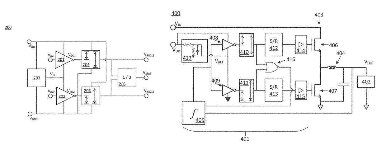
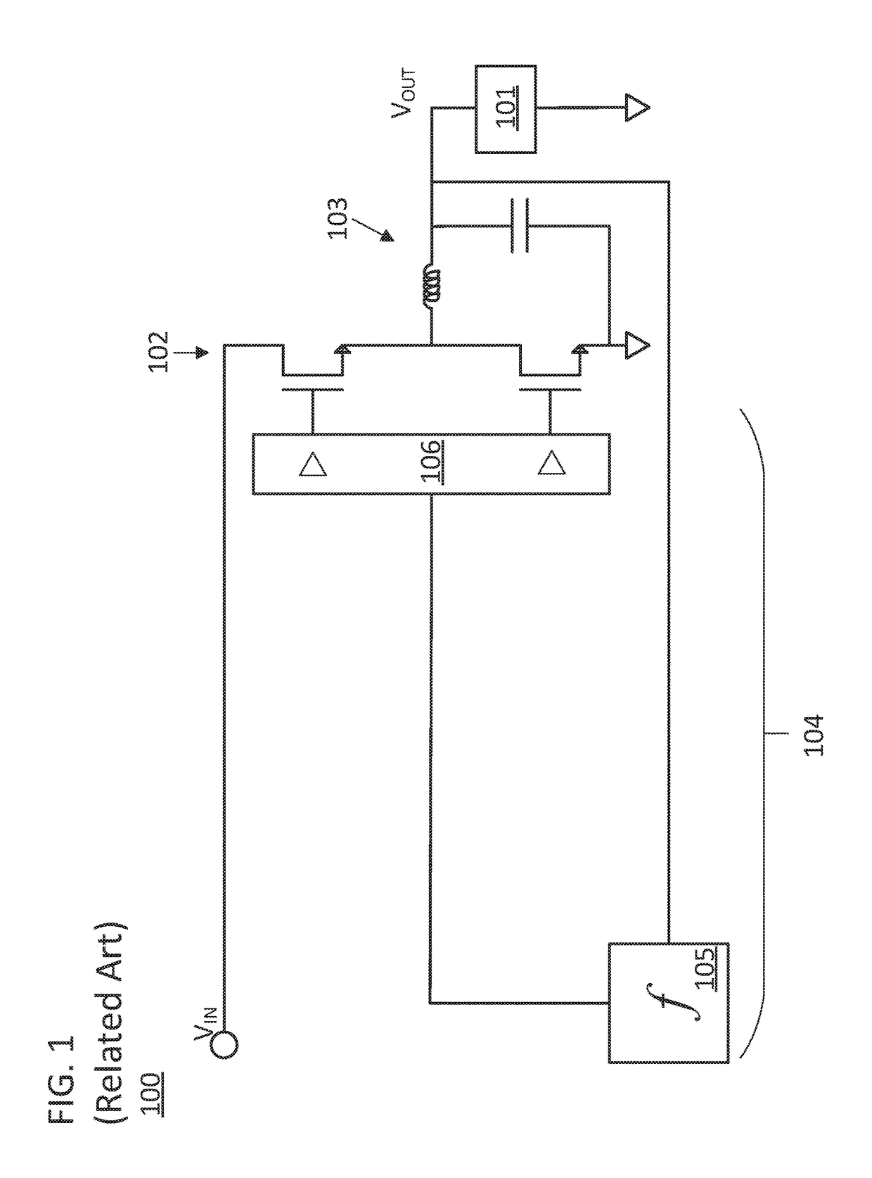
[0015]The switching circuit of a switched power converter deals with large system-level currents and relatively large voltages. Switching circuits that include two devices in series between the input and ground of the power converter, s...


PUM


Abstract

Various methods and devices that involve electronic circuits are disclosed. A disclosed method includes buffering an input signal using a first buffer. The first buffer is powered by a supply voltage and a reference voltage. The method also includes buffering the input signal using a second buffer. The second buffer is powered by the reference voltage and a ground voltage. The method also includes level shifting a first buffer output signal of the first buffer to a voltage range using a first level shifter, and level shifting a second buffer output signal of the second buffer to the voltage range using a second level shifter. The voltage range is larger than a delta between the supply voltage and the reference voltage. The reference voltage is greater than one quarter of the supply voltage and less than three quarters of the supply voltage.

Description

BACKGROUND OF THE INVENTION[0001]Electronic devices often need to generate multiple power regimes while only being powered by a single source. For example, a laptop computer may only have a single battery but may need to produce power regimes with different supply voltages for the various components on the laptop. Furthermore, regardless of the need for multiple power regimes, electronic devices often need to condition the power that is delivered to them from an external source. Returning to the example of a laptop, the laptop processor contains sensitive electronics and exhibits a widely varying power demand based on how hard the processor is working. Simply plugging in a DC version of the mains voltage source is not an option because the processor will not be shielded from dips or surges in the power supply and the power supply will likewise not be able to keep pace with the rapid transitions in the power drawn by the processor. The aforementioned requirements are addressed by pow...

Claims


Application Information

Patent Timeline
IPC IPC(8): H02M3/158H02M1/08H02M1/088H02M1/096H03K19/0175H03K17/687
CPCH02M3/158H03K19/017509H03K17/687H02M3/1588Y02B70/10
Inventor NEWLIN, TREVOR M.
Owner SILANNA ASIA
Why Eureka
Try Eureka