
Multi-section portable electronic torch

a portable electric torch and multi-section technology, applied in the direction of electric lighting with batteries, semiconductor devices for light sources, light and heating apparatus, etc., can solve the problems of accidental starting fire, burning to the torch user, and combustible materials being set on fir

Active Publication Date: 2017-07-18
ZYNTONY INC
View PDF2 Cites 22 Cited by
  • Summary
  • Abstract
  • Description
  • Claims
  • Application Information

AI Technical Summary

Benefits of technology

The patent text describes an electronic torch that has multiple sections that can be independently activated using light emitting diodes. This torch can be controlled by a mobile device that connects to it and provides instructions. The technical effect of this invention is the ability to have a more versatile and controllable electronic torch system.

Problems solved by technology

The combustible material may be set on fire.
Unfortunately, as the combustible material on the torch is consumed by fire, conventional torches would drop burned combustible material which could result in burns to a torch user or could result in unintentionally starting a fire.
Flashlights and lanterns, however, share light focusing problems.
Flashlights, on one hand, provide a relatively narrowly focused beam of light, which results in fairly intense light in a single direction.
However, the flashlight provides very little ambient light to illuminate the user's surroundings.
On the other hand, lanterns generally have no light focusing ability.
However, a lantern provides very little light at a distance.
Further, when held by a user, a lantern generally emits light back into the eyes of the user, reducing the user's night vision.
Not only does emitting light into the eyes of a user make it more difficult for the user to see beyond the illumination radius of the lantern, but lanterns are also generally held by a handle on the top which places the lantern at eye level, maximizing the amount of light being emitted into the eyes of the user.
Thus, while flashlights and lanterns provide some utility in various situations, neither flashlights nor lanterns are useful in some situations.
For example, flashlights cannot illuminate an entire campsite while a lantern cannot illuminate a significant length of a trail.

Method used


Image

  • Multi-section portable electronic torch
  • Multi-section portable electronic torch
  • Multi-section portable electronic torch

Examples


Embodiment Construction

[0026]In the following description, for purposes of explanation and not limitation, specific techniques and embodiments are set forth, such as particular techniques and configurations, in order to provide a thorough understanding of the device disclosed herein. While the techniques and embodiments will primarily be described in context with the accompanying drawings, those skilled in the art will further appreciate that the techniques and embodiments may also be practiced in other similar devices.

[0027]Reference will now be made in detail to the exemplary embodiments, examples of which are illustrated in the accompanying drawings. Wherever possible, the same reference numbers are used throughout the drawings to refer to the same or like parts. It is further noted that elements disclosed with respect to particular embodiments are not restricted to only those embodiments in which they are described. For example, an element described in reference to one embodiment or figure, may be alt...


PUM


Abstract

An electronic torch is disclosed which includes at least one light emitting diode disposed in each one of a plurality of sections of the electronic torch. In one embodiment, each one of the plurality of sections of the electronic torch is independently selectable to activate the at least one light emitting diode disposed in each one of the plurality of sections of the electronic torch. In another embodiment, a mobile device may be connected to the electronic torch and provide instructions to the torch via a wired or wireless connection.

Description

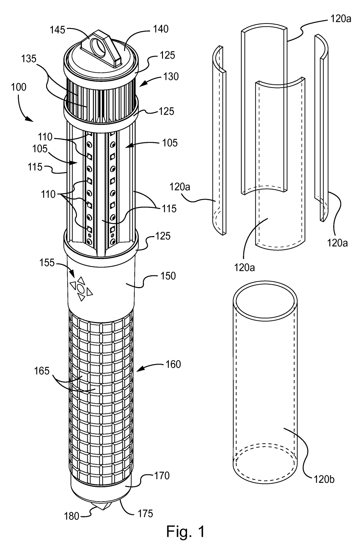
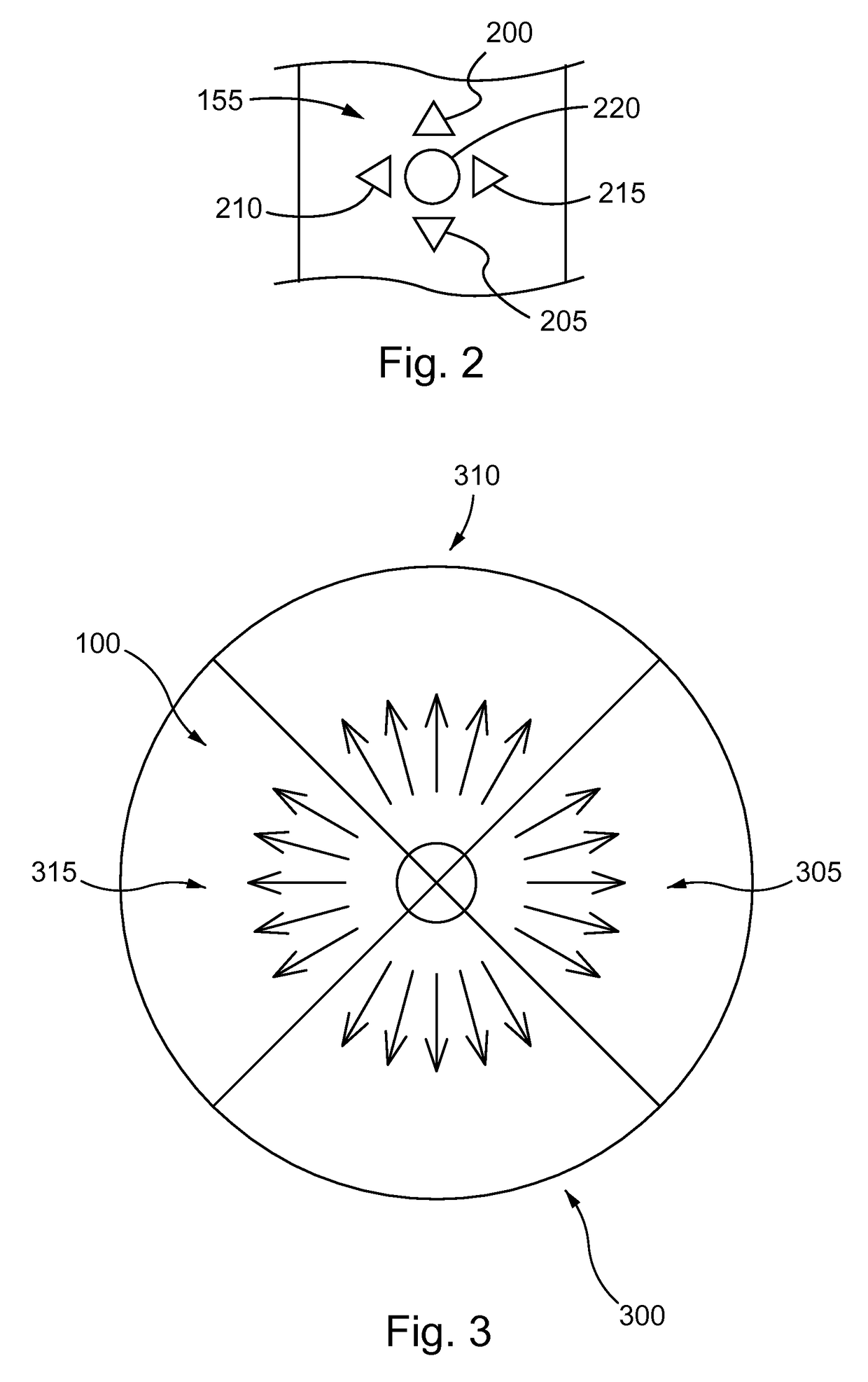
BACKGROUND[0001]1. Technical Field[0002]This disclosure relates generally to a multi-section portable electric torch. More specifically, the multi-section portable electric torch provides light using a light emitting system designed to selectively emit light in various directions. The multi-section portable electric torch is controlled using a multi-function user button or wirelessly. The multi-section portable electric torch is rechargeable and may act as a power source to other devices.[0003]2. Description of the Related Art[0004]The word “torch” as used herein refers to the American usage of the term and should not be confused with other uses (e.g., British usage) of the term torch in connection with flashlights. Conventional torches are made of wooden sticks which are treated, on one end with a combustible material. The combustible material may be set on fire. While the combustible material burns, the torch emits light. Torches are generally held over the user's head, emitting l...

Claims


Application Information

Patent Timeline
Patent Type & Authority Patents(United States)
IPC IPC(8): H05B37/00H05B41/00H05B33/08H05B37/02F21L4/08H05B39/00F21V23/04F21V33/00F21L4/02H05B44/00F21Y103/10F21Y115/10
CPCH05B33/0845F21L4/02F21L4/08F21V23/0414F21V23/0435F21V33/00H05B37/0272F21Y2103/10F21Y2115/10F41B13/08F41B15/08H05B45/10H05B47/19H05B45/3725H05B47/1965H05B47/1985
Inventor URRY, ROBINJOHNSEN, ROGERSCOTT, RUSSELLDAVIS, JAY
Owner ZYNTONY INC
Learn More