
Switch device with multiple water outputs

a technology of a switch and a water output, which is applied in the direction of valve operating means/releasing devices, mechanical equipment, transportation and packaging, etc., can solve the problem that the maximum four water outputs are still not enough to meet users' expectations, and achieve the effect of simple structure and easy control

Inactive Publication Date: 2017-07-25
RUNNER XIAMEN CORP
View PDF12 Cites 5 Cited by
  • Summary
  • Abstract
  • Description
  • Claims
  • Application Information

AI Technical Summary

Benefits of technology

The device provides a simple and easy-to-control mechanism for achieving multiple water outputs, enhancing user flexibility and meeting diverse user needs by allowing for different combinations of open holes, thereby increasing the number of available water outputs.

Problems solved by technology

However, even the maximal four water outputs are still not enough to meet users' expectation in their daily life.
Moreover, because of limited space on the down plate of the switch device, the down plate doesn't have water output, through the switch device connected with different water output hole, and have different water outputs.

Method used


Image

  • Switch device with multiple water outputs
  • Switch device with multiple water outputs
  • Switch device with multiple water outputs

Examples


embodiment 1

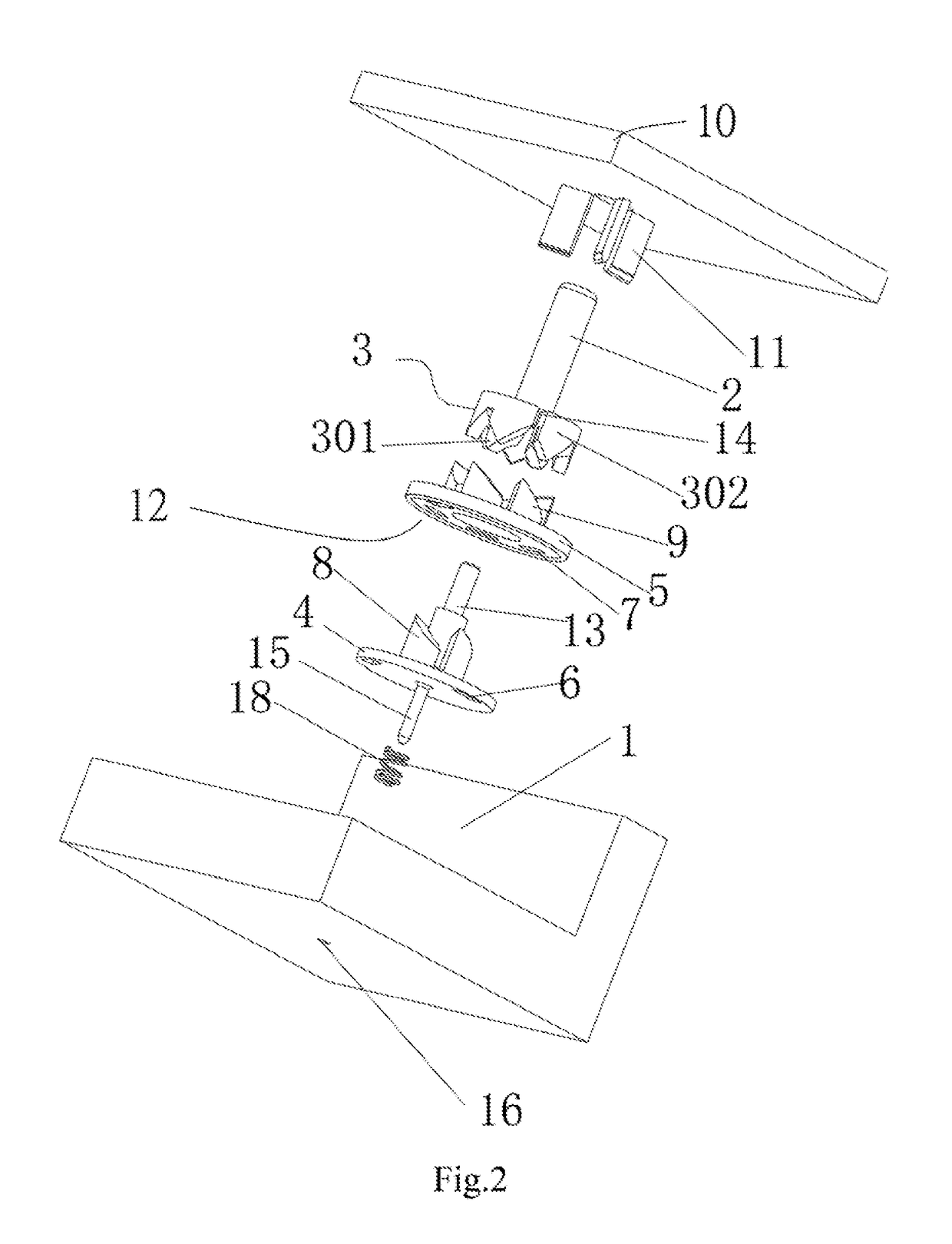
[0029]With reference to FIG. 3, the first teeth 8 of the first rotary plate 1 engage the inner toothed ring 301. The first rotary plate 4 has three first holes 6, and two of the first holes 6 located next to each other, which are selected to be open and correspond to two operation positions, are spaced apart from each other by the inner deviation angle, which is 120°. The second teeth 9 of the second rotary plate 2 engage the outer toothed ring 302. The second rotary plate 5 has six second holes 7, and four of the second holes 7 located next to one another or at every other second hole 7, which are selected to be open and correspond to four operation positions, are spaced apart from one another by the outer deviation angle, which is 60°, or double of the outer deviation angle, which is 120°.

embodiment 2

[0030]With reference to FIGS. 4 and 5, the first teeth 8 of the first rotary plate 1 engage the inner toothed ring 301. The first rotary plate 4 has three first holes 6, and two of the first holes 6 next to each other that are selected to be open and correspond to two operation positions are spaced apart from each other by the inner deviation angle, which is 120°. The second teeth 9 of the second rotary plate 2 engage the outer toothed ring 302. The second rotary plate 5 has six second holes 7, and five of the second holes 7 next to each other, which are selected to be open and correspond to five operation positions, are spaced apart from one another by the outer deviation angle, which 60°.

embodiment 3

[0031]With reference to FIG. 6, the first teeth 8 of the first rotary plate 1 engage the inner toothed ring 301. The first rotary plate 4 has four first holes 6, and two of the first holes 6 located at every other first hole 6, which are selected to be open and correspond to two operation positions, are spaced apart from each other by double of the inner deviation angle, which is 180°. The second teeth 9 of the second rotary plate 2 engage the outer toothed ring 302. The second rotary plate 5 has eight second holes 7, and six of the second holes 7 located next to each other, which are selected to be open and correspond to six operation positions, are spaced apart from one another by the outer deviation angle, which is 45°.


PUM


Abstract

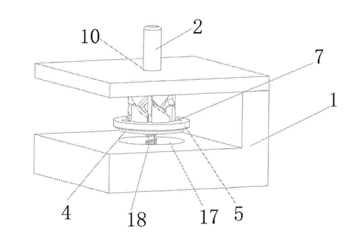
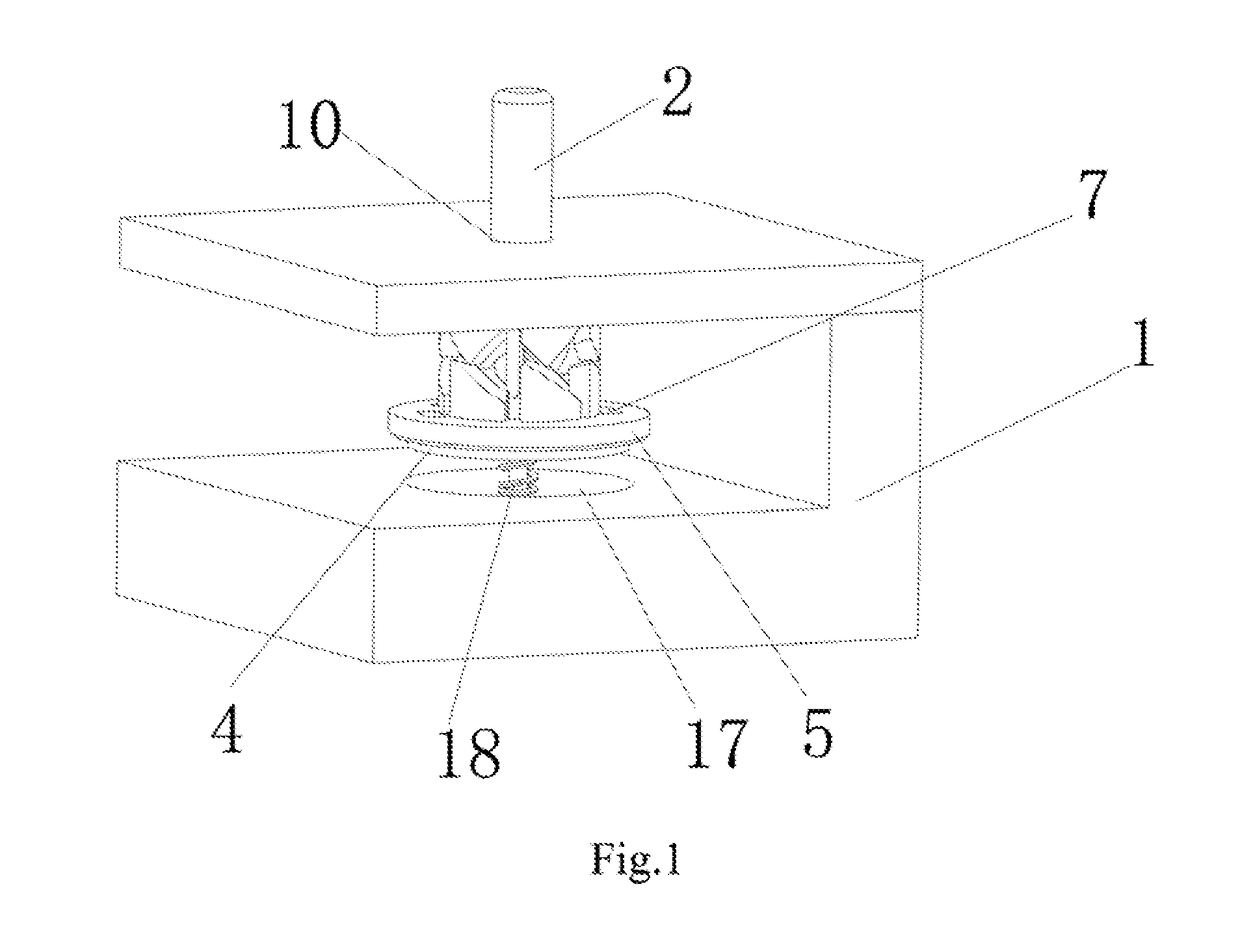
A switch device with multiple water outputs includes a switch valve, a rotary rod, an engagement ring, a first rotary plate and a second rotary plate. The rotary rod is mounted through an opening of the switch valve. The engagement ring has an inner toothed ring and an outer toothed ring formed on a bottom end of the rotary rod. The first rotary plate and the second rotary plate respectively engage the inner toothed ring and the outer toothed ring, and the both rotary plates have multiple holes. As water entering the holes with different number and deviation angle of the first and second rotary plate selectively communicate with each other, different water outputs can be provided.

Description

BACKGROUND OF THE INVENTION[0001]Field of the Invention[0002]The present invention relates a to a switch device and, more particularly, to a switch device with multiple water outputs.[0003]Description of the Related Art[0004]Currently, faucets in kitchen adopt a handle to switch a top and down plate to have different water outputs ranging from two to four different water outputs. However, even the maximal four water outputs are still not enough to meet users' expectation in their daily life. Moreover, because of limited space on the down plate of the switch device, the down plate doesn't have water output, through the switch device connected with different water output hole, and have different water outputs.SUMMARY OF THE INVENTION[0005]In view of the problems and drawbacks of the prior art, the objective of the present invention is to provides a switch device with multiple water outputs featuring a simple structure, easy control and multiple water outputs.[0006]To achieve the foreg...

Claims


Application Information

Patent Timeline
Patent Type & Authority Patents(United States)
IPC IPC(8): E03C1/04B05B1/18F16K11/074B05B1/16B05B12/00F16K31/524E03C1/02
CPCF16K11/074F16K31/52475E03C1/0405B05B1/1636B05B1/18B05B12/002E03C2001/026Y10T137/86501F16K31/523
Inventor HUANG, HUAN-LONGYE, WEN-HUAZHUO, ZHAO-YI
Owner RUNNER XIAMEN CORP
Learn More