High bandwidth large surface area ultrasonic block horn

a large surface area and ultrasonic block technology, applied in the field of ultrasonic welders, can solve the problems of ultrasonic power supply overload, low bandwidth ultrasonic stacks, and very low bandwidth, and achieve the effects of high bandwidth, higher coupling coefficient (keff), and high bandwidth

Inactive Publication Date: 2017-08-01
BRANSON ULTRASONIC CORP
View PDF22 Cites 0 Cited by
  • Summary
  • Abstract
  • Description
  • Claims
  • Application Information

AI Technical Summary

Benefits of technology

[0028]A large surface area slotted ultrasonic block horn formed of a plurality of the above described shaped elements achieves high bandwidth when used in a typical ultrasonic stack as it provides the ultrasonic stack with a higher coupling coefficient (Keff) compared to existing large surface area ultrasonic horns. The higher Keff is achieved due to lower strain energy being needed for the large surface area ultrasonic block horn to operate a given ultrasonic frequency.

Problems solved by technology

That is, the ultrasonic horn causes oscillatory compression / decompression of the plastic pieces with respect to each other causing surfaces of the plastic pieces abutting each other at a weld interface to be heated, eventually melting together.
Using ultrasonic horns with these high quality factors lead to ultrasonic stacks that have very low bandwidth.
Low bandwidth ultrasonic stacks are problematic for ultrasonic power supplies to track and maintain axial resonance during typical weld cycles.
This can result in overloads of the ultrasonic power supplies due to the difficulties in tuning and tracking the resonant frequency.

Method used


Image

  • High bandwidth large surface area ultrasonic block horn
  • High bandwidth large surface area ultrasonic block horn
  • High bandwidth large surface area ultrasonic block horn

Examples


Embodiment Construction

[0026]Example embodiments will now be described more fully with reference to the accompanying drawings.

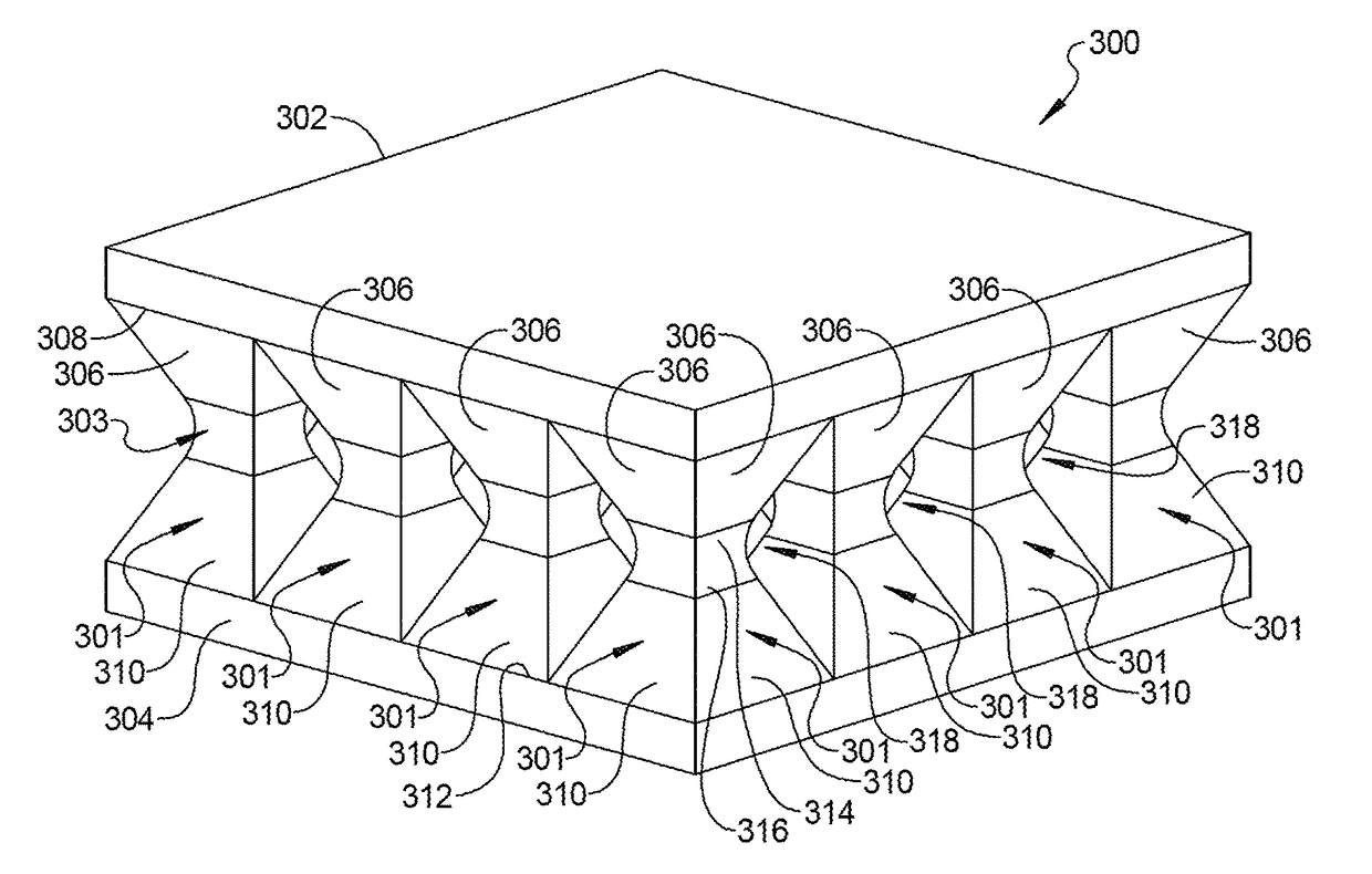
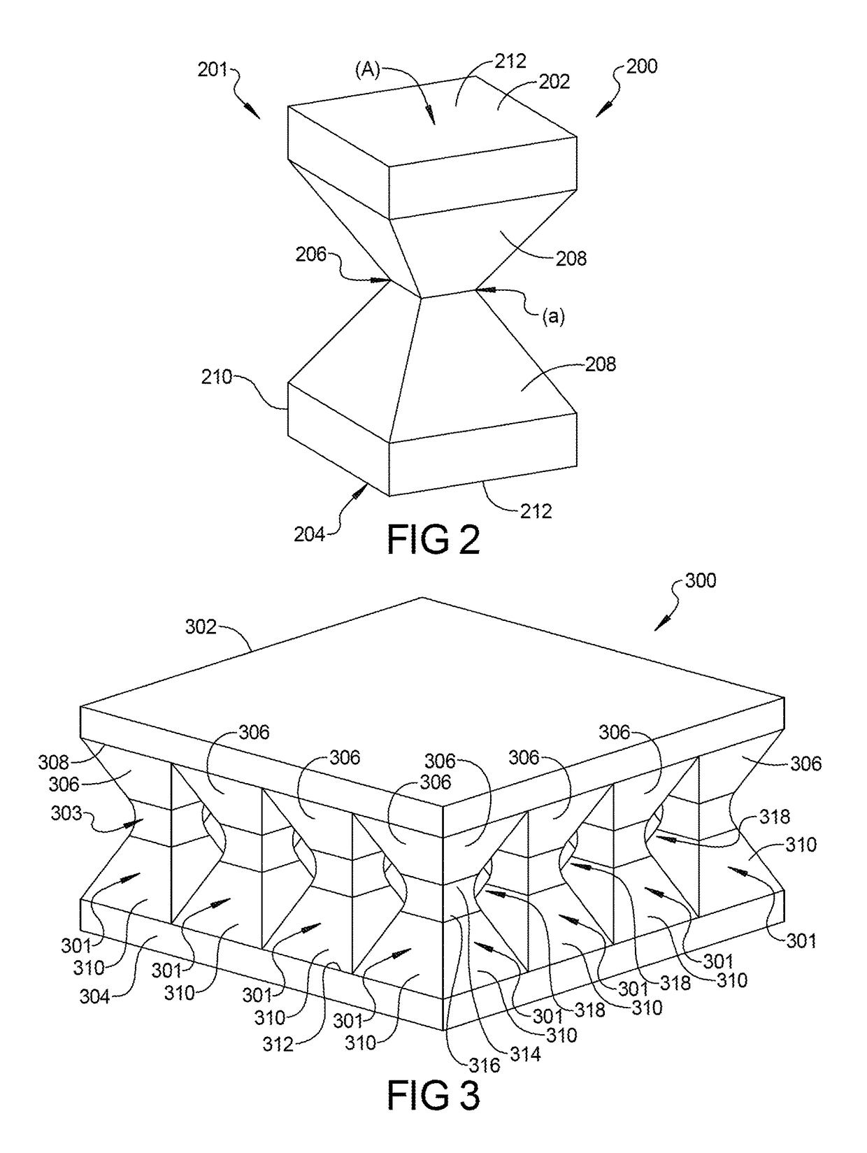
[0027]In accordance with an aspect of the present disclosure, a large surface area ultrasonic block horn includes one or more shaped elements having a node at a mid-point of the shaped element that is narrower than opposed ends of the shaped element. “Large surface area” in this context means that the ultrasonic block horn has a length or width equal to or greater than ½ the nominal resonant frequency of the ultrasonic stack in which the ultrasonic block horn is intended to be used. The mid-point of the shaped element is the point that is equidistant from the opposed ends. The areas of the opposed ends are thus larger than an area of the node, which is the cross-sectional area of shaped element at the mid-point. In an aspect, the shaped element is symmetrical about the node. That is, halves of the shaped element on either side of the node are symmetrical. In an aspect, when the lar...


PUM

PropertyMeasurementUnit
frequencyaaaaaaaaaa
frequencyaaaaaaaaaa
frequencyaaaaaaaaaa

Abstract

A large surface area ultrasonic block horn includes one or more shaped elements having a node at a mid-point of the shaped element that is narrower than opposed ends of the shaped element.

Description

CROSS-REFERENCE TO RELATED APPLICATIONS[0001]This application claims the benefit of U.S. Provisional Application No. 62 / 009431, filed on Jun. 9, 2014. The entire disclosure of the above application is incorporated herein by reference.FIELD[0002]The present disclosure relates to ultrasonic welders, and more particularly, to a high bandwidth ultrasonic horn for ultrasonic welders.BACKGROUND[0003]This section provides background information related to the present disclosure which is not necessarily prior art.[0004]A model of a typical prior art ultrasonic metal welding apparatus 100 is shown in FIG. 1. Typical components of ultrasonic metal welding apparatus 100 include an ultrasonic transducer 102, a booster 104, and an ultrasonic horn 106. The ultrasonic transducer 102, booster 104 and ultrasonic horn 106 comprise weld stack 118. It should be understood that in some cases, weld stack 118 does not have booster 104. Electrical energy from a power supply 101 at a frequency of 20-60 kHz ...

Claims


Application Information

Patent Timeline
Patent Type & Authority Patents(United States)
IPC IPC(8): B23K1/06B23K20/10B06B3/00B29C65/08
CPCB23K20/106B06B3/00B29C65/085
Inventor SHEEHAN, JAMES F.
Owner BRANSON ULTRASONIC CORP
Why Eureka
Try Eureka