Wire harness

a wire harness and wire technology, applied in the direction of cables, insulated conductors, conductors, etc., can solve the problems of labor-intensive and inefficient processes, and achieve the effect of convenient assembly and precise alignmen

Active Publication Date: 2017-08-01
SUMITOMO WIRING SYST LTD
View PDF5 Cites 0 Cited by
  • Summary
  • Abstract
  • Description
  • Claims
  • Application Information

AI Technical Summary

Benefits of technology

[0010]In light of the forgoing problems, aspects of the invention provide a wire harness that makes no use of twisted pair wires but is robust against electromagnetic noise, and is easier to assemble.
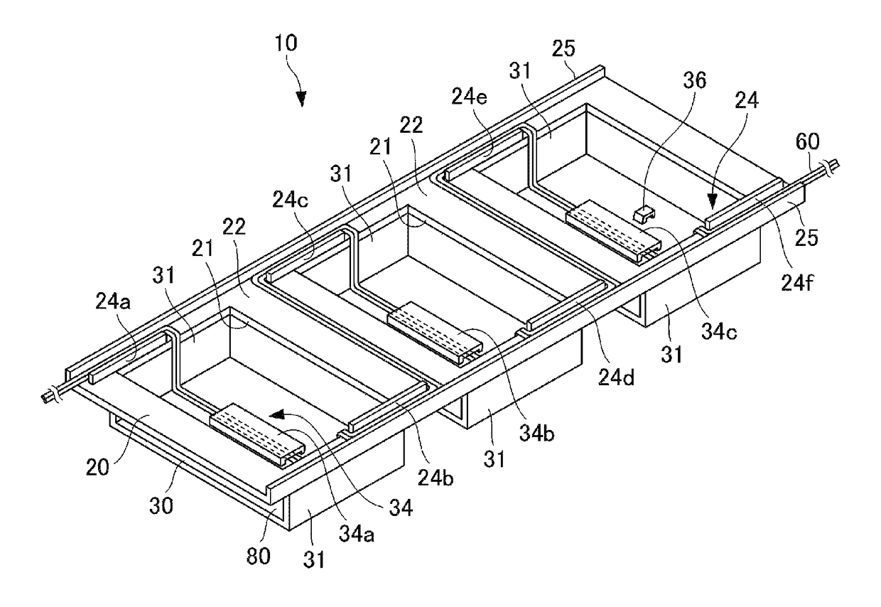
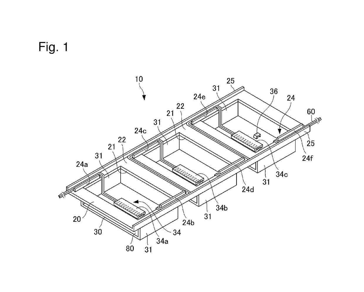
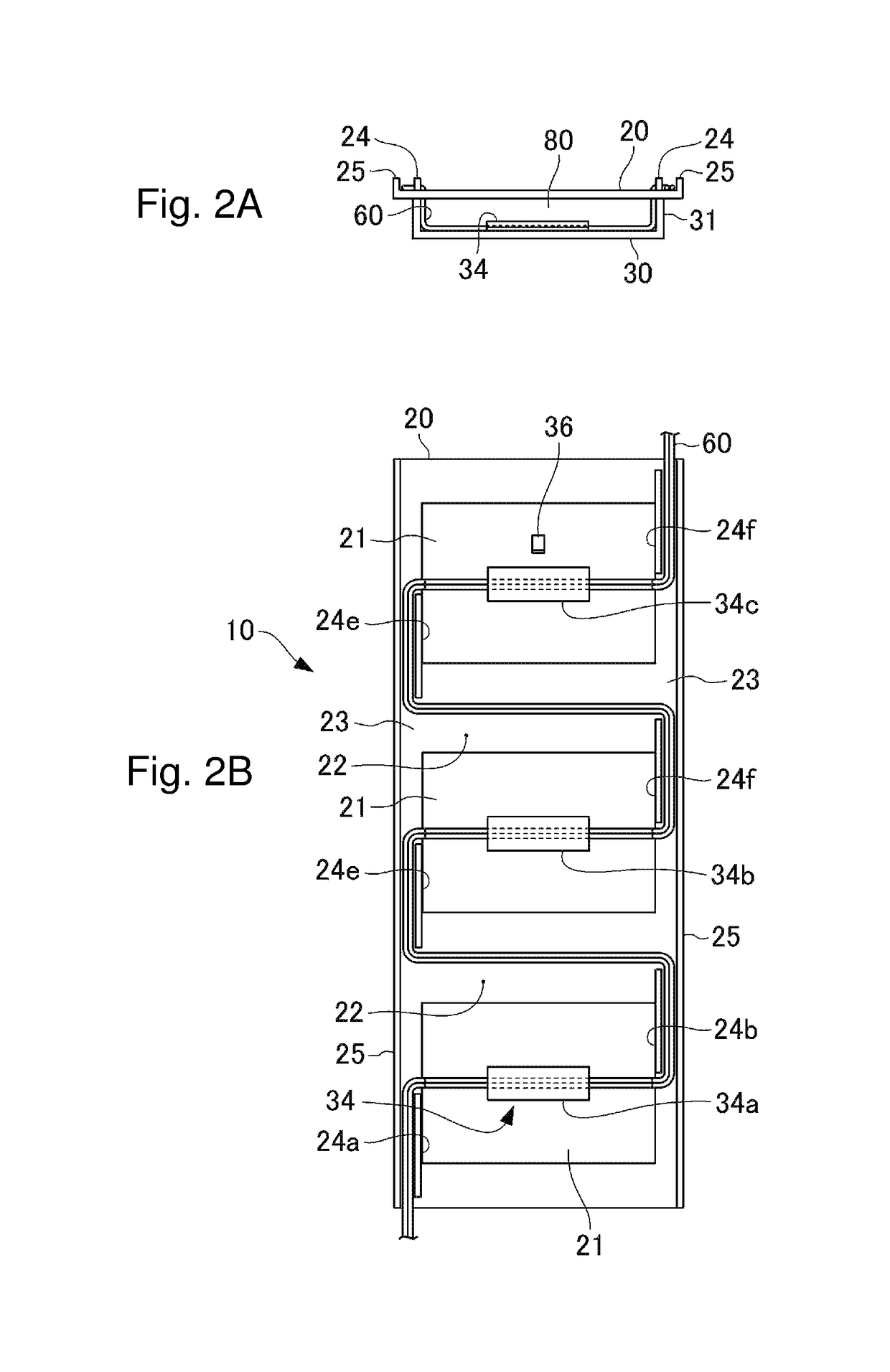
[0012]With this configuration, in a wire harness according to this aspect of the present invention, the first electric wire is three dimensionally routed along a first frame; a second electric wire is routed serpentine through the second frame; and the second frame is housed between the upper thin plate and the lower thin plates of the first frame. In this state, the first electric wire passes beneath the second electric wire at the above-mentioned openings. Additionally, the first electric wire passes below the second electric wire at the openings, and passes above the second electric wire at the connecting portions while passing on the connecting portions. That is, the first electric wire and the second electric wire can have a twist structure without performing the conventional wire twisting process. A noise-resistant wire harness can be easily manufactured at low cost since, with this configuration, it is possible to eliminate the typical labor-intensive processes such as twisting the electric wire, and the like.
[0014]With this configuration, the second frame in the wire harness according to this aspect will not shift relative to the first frame, thus enabling precise alignment and ensuring consistent performance of the wire harness in resisting noise.
[0015]An embodiment of the invention provides a wire harness that makes no use of twisted pair wires but is robust against electromagnetic noise, and is easier to assemble.

Problems solved by technology

These processes are labor-intensive and inefficient.

Method used


Image

  • Wire harness
  • Wire harness
  • Wire harness

Examples


Embodiment Construction

[0023]The particulars shown herein are by way of example and for purposes of illustrative discussion of the embodiments of the present invention only and are presented in the cause of providing what is believed to be the most useful and readily understood description of the principles and conceptual aspects of the present invention. In this regard, no attempt is made to show structural details of the present invention in more detail than is necessary for the fundamental understanding of the present invention, the description taken with the drawings making apparent to those skilled in the art how the forms of the present invention may be embodied in practice.

[0024]A wire harness according to an embodiment of the present invention is described below with reference to the drawings.

[0025]Configuration

[0026]A wire harness 1 according to the embodiment is provided with a first frame 10, a second frame 40, a first electric wire 60, and a second electric wire 70 as illustrated in FIG. 5 and...


PUM

PropertyMeasurementUnit
longitudinal lengthaaaaaaaaaa
distanceaaaaaaaaaa

Abstract

A first electric wire is fastened, in a first frame, by a plurality of first wire hooking ribs provided on upper side edges of an upper thin plate, and by a plurality of second wire hooking ribs provided at lower thin plates, thereby being routed three-dimensionally. A second electric wire is fastened, in a second frame, by a plurality of third wire hooking ribs provided staggered along the upper side edges of the second frame, thereby being routed in a serpentine shape. With the electric wires routed and the second frame accommodated at a predetermined location in a housing space of the first frame, the first electric wire passes below the second electric wire at openings in the structure and passes above the second electric wire at connecting portions in the structure while passing on the connecting portions.

Description

CROSS-REFERENCE TO RELATED APPLICATIONS[0001]The present application claims priority under 35 U.S.C. §119 of Japanese Application No. 2015-202865, filed on Oct. 14, 2015, the disclosure of which is expressly incorporated by reference herein in its entirety.BACKGROUND OF THE INVENTION[0002]1. Field of the Invention[0003]The present invention relates to a wire harness required for dealing with electromagnetic noise.[0004]2. Description of Related Art[0005]In recent years, vehicles are equipped with a plurality of various electronics, sensors, and electronic control units (ECU). An ECU controls the electronics and sensors installed in a vehicle. A variety of measures are taken to prevent electromagnetic noise from interfering with the signal lines interconnecting the ECUs and the various electronics and sensors, and the signal lines interconnecting the ECUs (for example, refer to Japanese Patent Laid-open Publication 2015-038838, FIG. 1, paragraphs 0002, 0008).[0006]Japanese Patent Lai...

Claims


Application Information

Patent Timeline
Patent Type & Authority Patents(United States)
IPC IPC(8): H02G3/02H01B7/00H01B11/00
CPCH01B7/0045H01B11/002H02G3/02B60R16/0215H02G3/0456
Inventor OIKAWA, SEIJIWAKABAYASHI, MASATAKA
Owner SUMITOMO WIRING SYST LTD
Why Eureka
Try Eureka