Continuous flow carboxylation reaction
a carboxylation reaction and continuous flow technology, applied in the formation/introduction of sulfonyl/sulfinyl groups, chemical/physical/physico-chemical processes, organic chemistry, etc., can solve the problem of violent polymerization of reactive benzyne intermediates, low isolated yield, and temperature sensitive effects
- Summary
- Abstract
- Description
- Claims
- Application Information
AI Technical Summary
Benefits of technology
Problems solved by technology
Method used
Image
Examples
example 1
Optimizing Reaction Conditions of Carboxylation Reaction
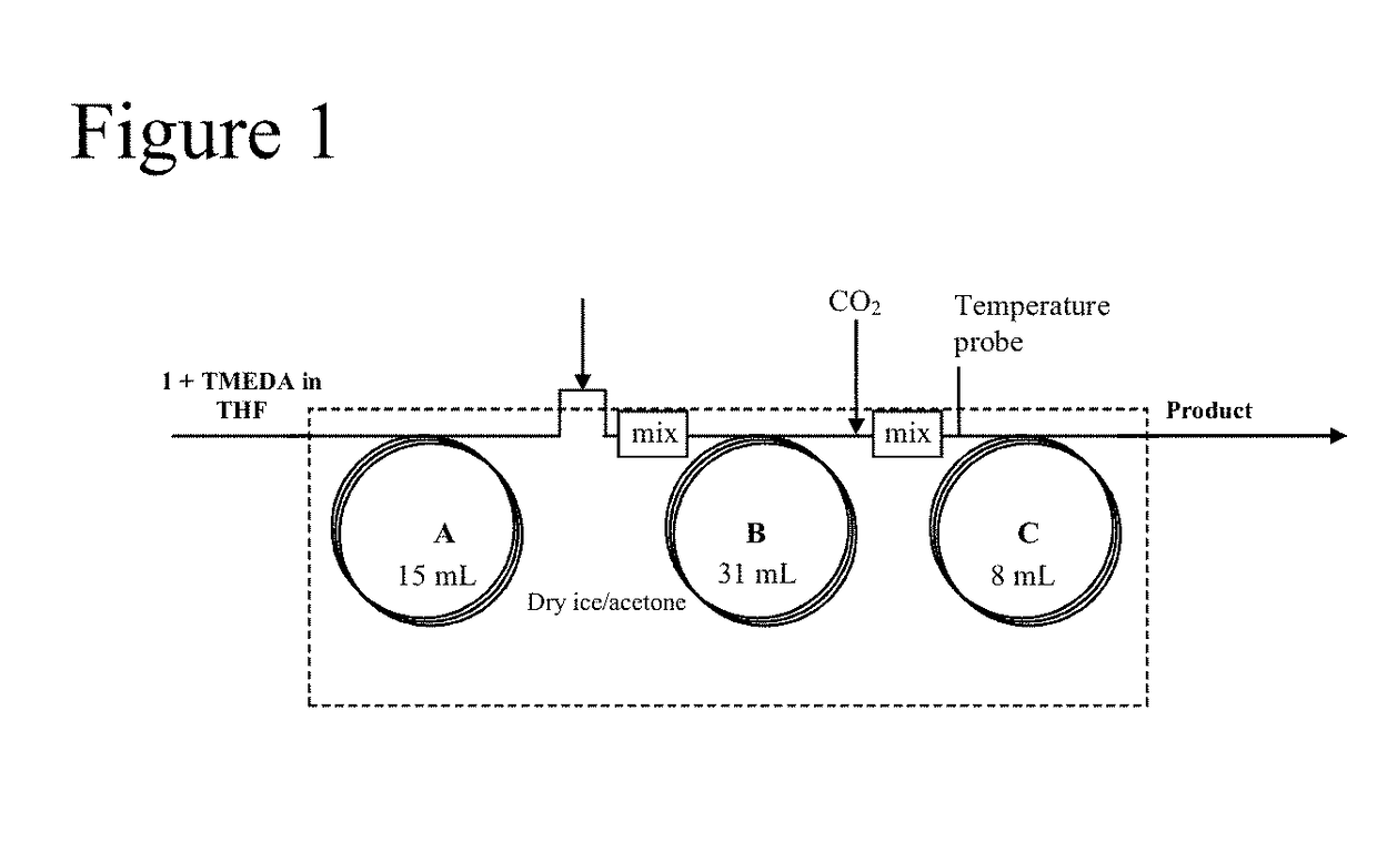
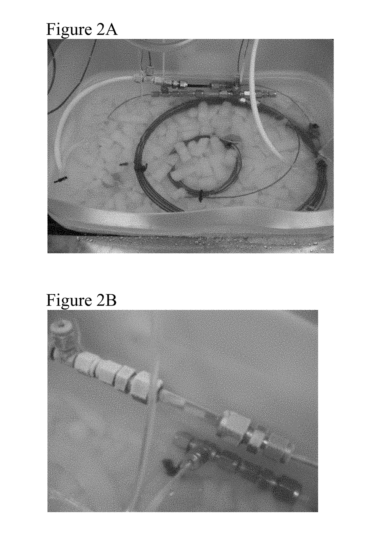
[0028]This example was performed using the reactor and mixer units shown in FIGS. 1 and 2. As shown in Table 1, an experiment was carried out to optimize the flow rates and residence times during the carboxylation reaction. Increasing the residence time for the carbon dioxide quench from 1 minute to 5 minutes was found to provide a dramatic increase in the conversion. Commercially available 1.5 MBuLi varied significantly in quality from lot to lot and flow rate had to be adjusted accounting for the lower potency of the reagent. This issue was overcome using a 2.5 M solution which was much more consistent in quality. Conditions were further optimized by increasing the concentration of 2 in THF to 10% and lowering the residence time for the anion formation to 10 minutes which showed >90% conversion. In attempts to further improve the throughput to process larger quantities of material, the same set up was designed using ¼ inch ID...
example 2
Optimization of Reactor Design
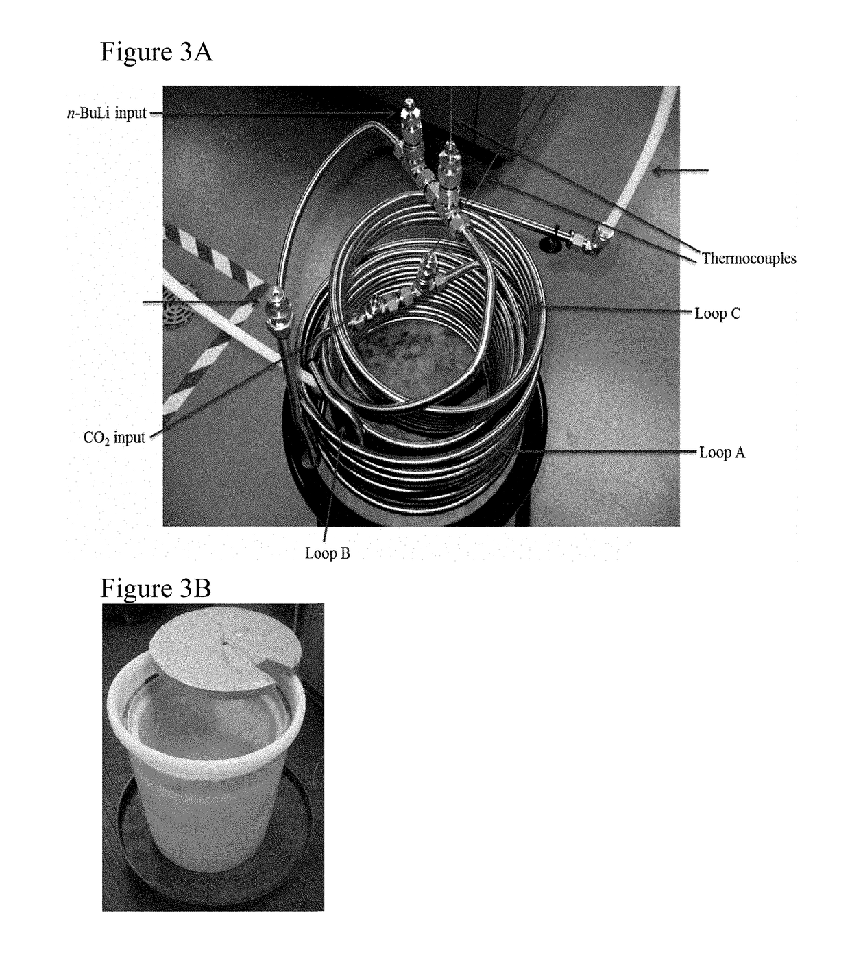
[0031]In this Example, the reactor described in Example 1 was optimized. An identical unit as in Example 1 was prepared with the exception that stainless steel tubes were used instead of HDPE tubes. Since the heat exchange in the case of stainless steel is higher than HDPE tubes it was envisioned that a much lower residence time (t1) would be required. The minimum tube length at maximum operatable flow rate required for complete heat dissipation was determined If l1 is the length needed to achieve the desired residence time and l2 is the length needed for complete heat dissipation, then the tube length is considered as the higher of the two. The length l1 is calculated based on the flow rate and the tube diameter. The length needed for complete heat dissipation (l2) for a known flow rate can be calculated from the following equation:
Q=UA ΔTlm [0032]Q—Heat Rate, BTU / hr; Q can be calculated according to the thermal properties of the process fluid (for pro...
example 3
Scale Up Reaction Using Optimized Reactor. Generation Reactor Set-Up
[0040]In this Example, large-scale reactions were performed using the reactor prepared in Example 2. Since the mixing using static mixer was more efficient, Applicants were able to further reduce the residence time by increasing the flow rates. Table 3 summarizes the details of the scale up runs.
[0041]
TABLE 3Results of Scale-Up Runs.Residence Time (min)Yield OverScaleAnionCO2PurityTwo StepsEntry(kg)FormationQuench(% AUC)(%)15.42.00.991.68123.52.00.994.4353.61.697.288443.61.698.291543.61.697.8
[0042]As shown in Table 3, the residence time for the anion formation was reduced 3.6 minutes and carbon dioxide quench to 1.6 minutes which gave the highest purity of 1.
[0043]Only two minor issues with the synthesis were observed. For example, (1) during the synthesis, valeric acid (a byproduct of the reaction of BuLi with carbon dioxide whose freezing point is −20° C.) froze in the lines and stopped the flow. However, this occ...
PUM
| Property | Measurement | Unit |
|---|---|---|
| reaction temperature | aaaaa | aaaaa |
| temperature | aaaaa | aaaaa |
| pressure | aaaaa | aaaaa |
Abstract
Description
Claims
Application Information
 - R&D
- Intellectual Property
- Life Sciences
- Materials
- Tech Scout
- Unparalleled Data Quality
- Higher Quality Content
- 60% Fewer Hallucinations
Browse by: Latest US Patents, China's latest patents, Technical Efficacy Thesaurus, Application Domain, Technology Topic, Popular Technical Reports.
© 2025 PatSnap. All rights reserved.Legal|Privacy policy|Modern Slavery Act Transparency Statement|Sitemap|About US| Contact US: help@patsnap.com


