Transcutaneous electrical nerve stimulator with automatic detection of leg orientation and leg motion for enhanced sleep analysis, including enhanced transcutaneous electrical nerve stimulation (TENS) using the same

a technology automatic detection of leg orientation and leg motion, which is applied in the field of transcutaneous electrical nerve stimulation (tens) devices, can solve the problems of inability to fully realize the effect of enhancing transcutaneous electrical nerve stimulation and improving sleep quality, and affecting sleep quality

Active Publication Date: 2017-08-15
NEUROMETRIX INC
View PDF86 Cites 31 Cited by
  • Summary
  • Abstract
  • Description
  • Claims
  • Application Information

AI Technical Summary

Benefits of technology

[0026]Significantly, it has now been recognized that the placement of a novel, accelerometer-equipped TENS device on the upper calf, with tight mechanical coupling to the upper calf, may be used to support novel approaches for detecting when the user is asleep, and novel metrics for analyzing the sleep of the user, and novel approaches to quantify body and leg motions associated with poor sleep quality and / or disorders such as restless leg syndrome, and novel approaches for providing enhanced transcutaneous electrical nerve stimulation (TENS) using the same. Among these novel metrics are “leg movements”, “body roll events” associated with rolling over in bed, and “time-on-back” which is relevant to users suffering not only from chronic pain but also from problematic sleep positions which can cause snoring or sleep apnea. In addition to tracking and reporting sleep indicators, real-time feedback to the user based on indicator trends can also help the user to improve sleep quality. An example is to provide an alert (via mechanical or electrical means, for example) to the user when time-on-back duration exceeds a threshold. Another example is to alter TENS stimulation parameters when leg movement patterns associated with discomfort caused by nighttime pain are detected in order to enhance the analgesic effect of TENS therapy.
[0028]The placement of the novel TENS device on the upper calf of the user is used to support novel approaches for detecting when the user is asleep, and for quantifying sleep and assessing abnormal body and leg motions, and for providing enhanced TENS therapy using such sleep analysis.
[0031]Third, the novel TENS device combines these two measures of leg orientation (i.e., leg elevation and leg rotation) and two measures of leg motion (i.e., net activity and leg movements) to improve sleep quantification and to utilize more precise quantification metrics to enhance therapeutic benefits.

Problems solved by technology

Chronic pain due to diabetic neuropathy and other causes can interfere with sleep, which carries a host of secondary complications.
Transcutaneous electrical nerve stimulation (TENS) devices provide pain relief by stimulating sensory nerves, which leads to an increase in endogenous opioids and down-regulation of pain signal transmission to the brain.
This limitation is evident in the design of conventional TENS devices, in which the electric current is delivered through wires (called leads) that are connected to electrode pads on the skin.
Such a design is not practical or safe for use during sleep because the leads are cumbersome and may get tangled or pulled, and because the electrode pads can potentially peel off the skin (which will terminate TENS therapy) or, perhaps worse, can potentially partially peel off the skin, leading to increased current density and negative consequences for the user (e.g., discomfort or, in extreme cases, burns).
Third, chronic pain can be persistent throughout the day, often worsening at night, and wearing the TENS device on the upper calf makes it discreet and unobtrusive, which encourages more regular use.
Most of these actigraphy-based devices are worn on the wrist however, and in certain ways that limits their ability to detect and quantify sleep.

Method used


Image

  • Transcutaneous electrical nerve stimulator with automatic detection of leg orientation and leg motion for enhanced sleep analysis, including enhanced transcutaneous electrical nerve stimulation (TENS) using the same
  • Transcutaneous electrical nerve stimulator with automatic detection of leg orientation and leg motion for enhanced sleep analysis, including enhanced transcutaneous electrical nerve stimulation (TENS) using the same
  • Transcutaneous electrical nerve stimulator with automatic detection of leg orientation and leg motion for enhanced sleep analysis, including enhanced transcutaneous electrical nerve stimulation (TENS) using the same

Examples


Embodiment Construction

The Novel TENS Device In General

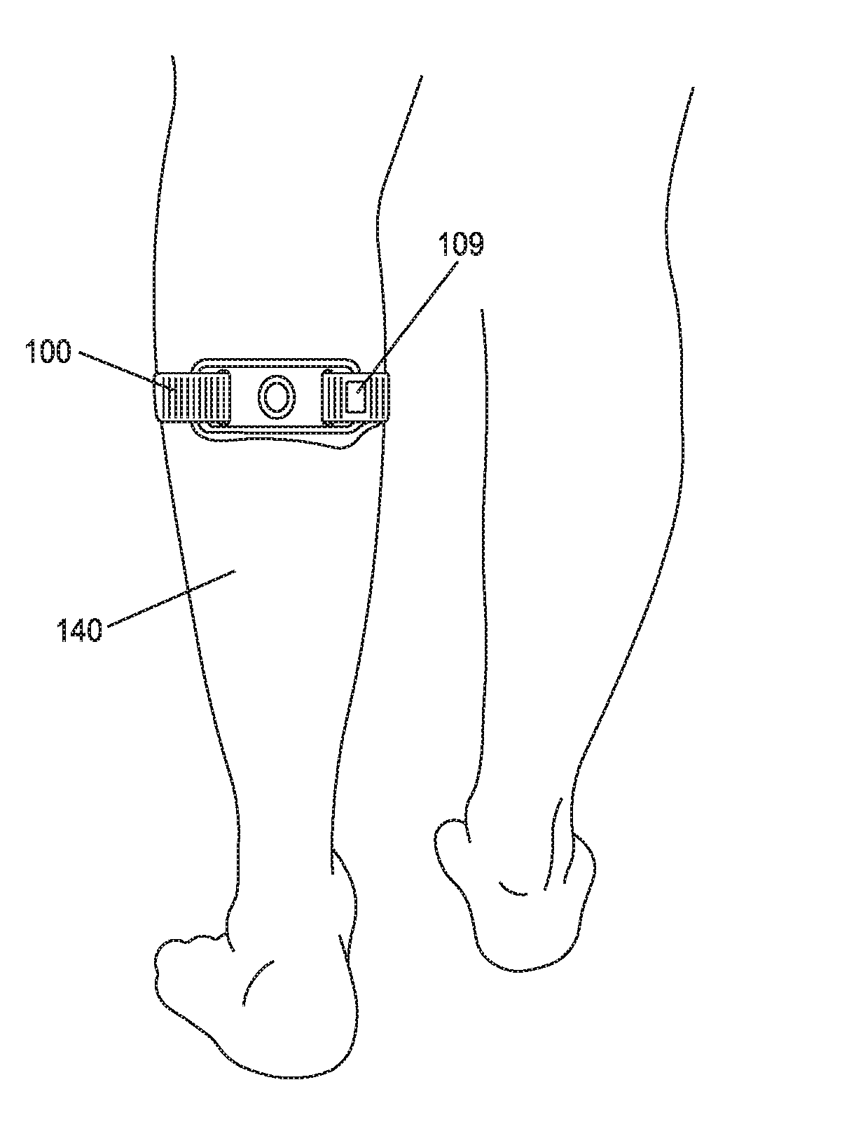
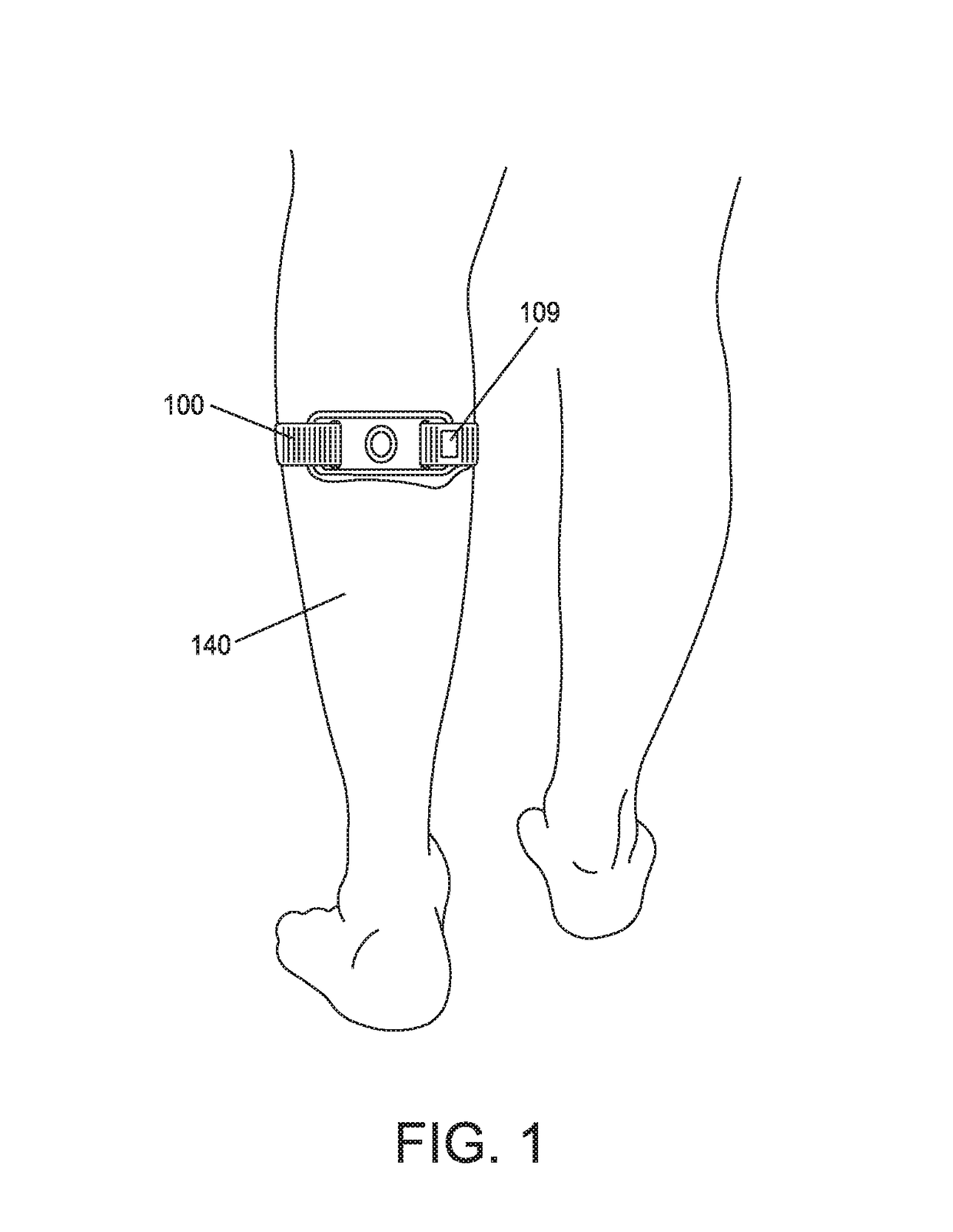
[0070]FIG. 1 illustrates a novel TENS device 100 formed in accordance with the present invention, with the novel TENS device being shown worn on a user's upper calf 140. A user may wear TENS device 100 on either leg.

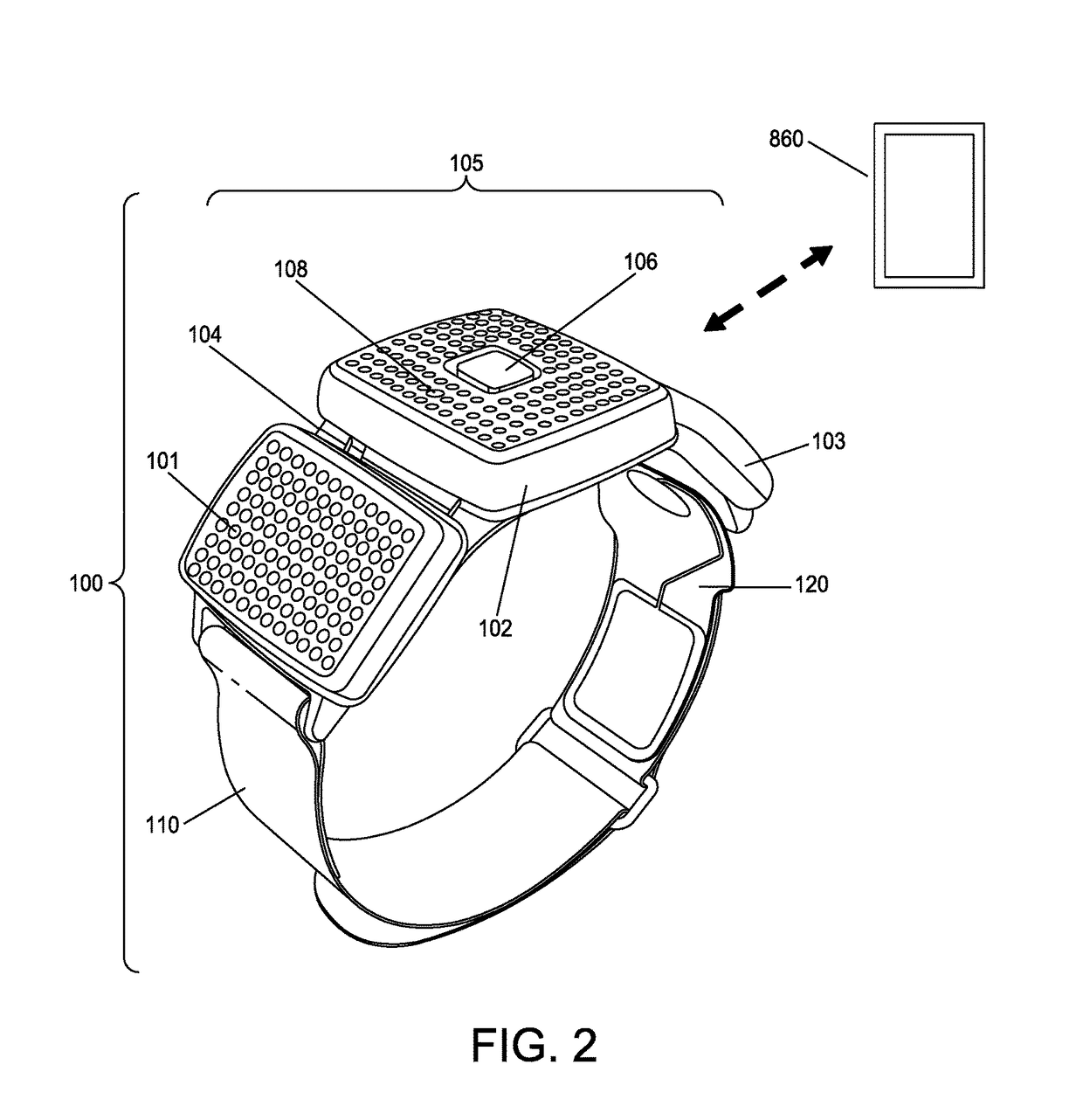
[0071]TENS device 100 is shown in greater detail in FIG. 2 and preferably comprises three primary components: a stimulator 105, a strap 110, and an electrode array 120 (comprising a cathode electrode and an anode electrode appropriately connected to stimulator 105 as is well known in the art). Stimulator 105 preferably comprises three mechanically and electrically inter-connected compartments 101, 102, and 103. Compartments 101, 102, 103 are preferably inter-connected by hinge mechanisms 104 (only one of which is shown in FIG. 2), thereby allowing TENS device 100 to conform to the curved anatomy of a user's leg. In a preferred embodiment of the present invention, compartment 102 houses the TENS stimulation circuitry (except for a battery) ...


PUM


Abstract

Apparatus for providing transcutaneous electrical nerve stimulation (TENS) therapy to a user, the apparatus comprising: a housing; an application unit for providing mechanical coupling between the housing and the user's body; a stimulation unit for electrically stimulating at least one nerve of the user; a sensing unit for sensing the user's body movement and body orientation; and a reporting unit for providing the user with feedback based on the user's sensed body movement and body orientation.

Description

REFERENCE TO PENDING PRIOR PATENT APPLICATIONS[0001]This patent application:[0002](1) is a continuation-in-part of pending prior U.S. Patent Application Publication No. 2015 / 0306387, filed Jul. 8, 2015 by NeuroMetrix, Inc. and Xuan Kong et al. for MEASURING THE “ON-SKIN” TIME OF A TRANSCUTANEOUS ELECTRICAL NERVE STIMULATOR (TENS) DEVICE IN ORDER TO MINIMIZE SKIN IRRITATION DUE TO EXCESSIVE UNINTERRUPTED WEARING OF THE SAME, which patent application:[0003](A) is a continuation-in-part of pending prior U.S. Patent Application Publication No. 2015 / 0148865, filed Jan. 30, 2015 by NeuroMetrix, Inc. and Shai N. Gozani et al. for APPARATUS AND METHOD FOR RELIEVING PAIN USING TRANSCUTANEOUS ELECTRICAL NERVE STIMULATION, which patent application:[0004](i) is a continuation of prior U.S. Pat. No. 8,948,876, filed Nov. 15, 2012 by NeuroMetrix, Inc. and Shai N. Gozani et al. for APPARATUS AND METHOD FOR RELIEVING PAIN USING TRANSCUTANEOUS ELECTRICAL NERVE STIMULATION, which patent application c...

Claims


Application Information

Patent Timeline
Patent Type & Authority Patents(United States)
IPC IPC(8): A61N1/36A61N1/04A61B5/11A61B5/00A61N1/32
CPCA61N1/36021A61B5/1116A61B5/4815A61B5/6828A61B5/6831A61N1/0456A61N1/0476A61N1/0492A61N1/321A61N1/36014A61N1/36031A61N1/36034A61B5/4809A61B5/11
Inventor FERREE, THOMASGOZANI, SHAIKONG, XUAN
Owner NEUROMETRIX INC
Why Eureka
Try Eureka