
Use of treating elements to facilitate flow in vessels

Active Publication Date: 2017-08-15
CRYSTAPHASE PRODS
View PDF11 Cites 16 Cited by
  • Summary
  • Abstract
  • Description
  • Claims
  • Application Information

AI Technical Summary

Benefits of technology

The patent text describes a method for improving the distribution and redistribution of streams in a bed vessel. The method involves using redistribution treating zones with solid processing material elements and treating materials to efficiently disperse the flow of streams and improve contact with the solid processing material elements in the downstream processing zones. The method can lead to improved performance and utilization of the bed vessel compared to configurations without the redistribution treating zones. The solid processing material elements can migrate into the redistribution treating zones and commingle with the treating elements, creating a combo-zone with both solid processing material elements and treating elements and their functionalities.

Problems solved by technology

Many bed vessels face challenges associated with sustaining effective and efficient utilization of bed vessel internals including effective and efficient stream flow distribution across and throughout the beds of solid processing material elements installed in the bed vessels.
Inadequate stream flow distribution leads to coalescence of small stream rivulets into larger streams resulting in stream flow channeling which can result in bypassing portions of the bed vessel processing internals.
Stream flow channeling within a bed vessel can occur and change over time due to shifts in operating conditions (e.g., changing compositions of feed streams), operations upsets (e.g., power surges / cuts, pump failures, etc.), natural or accelerated aging of bed vessel internals and the like.
Channeling is undesirable because it results in areas of underexposed and underutilized bed vessel internal materials and areas of overexposed materials.
The former can result in significant loss of bed vessel productivity and profitability.
The latter can result in so-called “hot spots” where sharp temperature gradients cause damage to the vessel and its internals.
This mode of operation results in reduced “on-oil” operating time with accompanying loss of bed vessel productivity and profitability.
Such devices are costly to design, fabricate, install, operate and maintain and requires specially-trained personnel to do so.
These conventional devices also require complex monitoring and containment systems to ensure segregation from other bed vessel internals.
Any loss of catalyst containment can result in process and safety risks.
The very presence of such conventional redistribution and containment equipment and the difficulty of sustaining their stable and controlled operation can lead to problems up to and including development of bed vessel shell hot spots leading potentially to rupture of the bed vessel itself.
The very presence of such conventional structured engineered devices consumes space that could otherwise be consumed by more productive and more profitable bed vessel internals, such as catalyst.
Such migration is typically limited to the first few inches of depth of the redistribution treating zone materials.
Such migration is typically limited to the first few inches of the redistribution treating zone materials.

Method used


Image

  • Use of treating elements to facilitate flow in vessels
  • Use of treating elements to facilitate flow in vessels
  • Use of treating elements to facilitate flow in vessels

Examples


Embodiment Construction

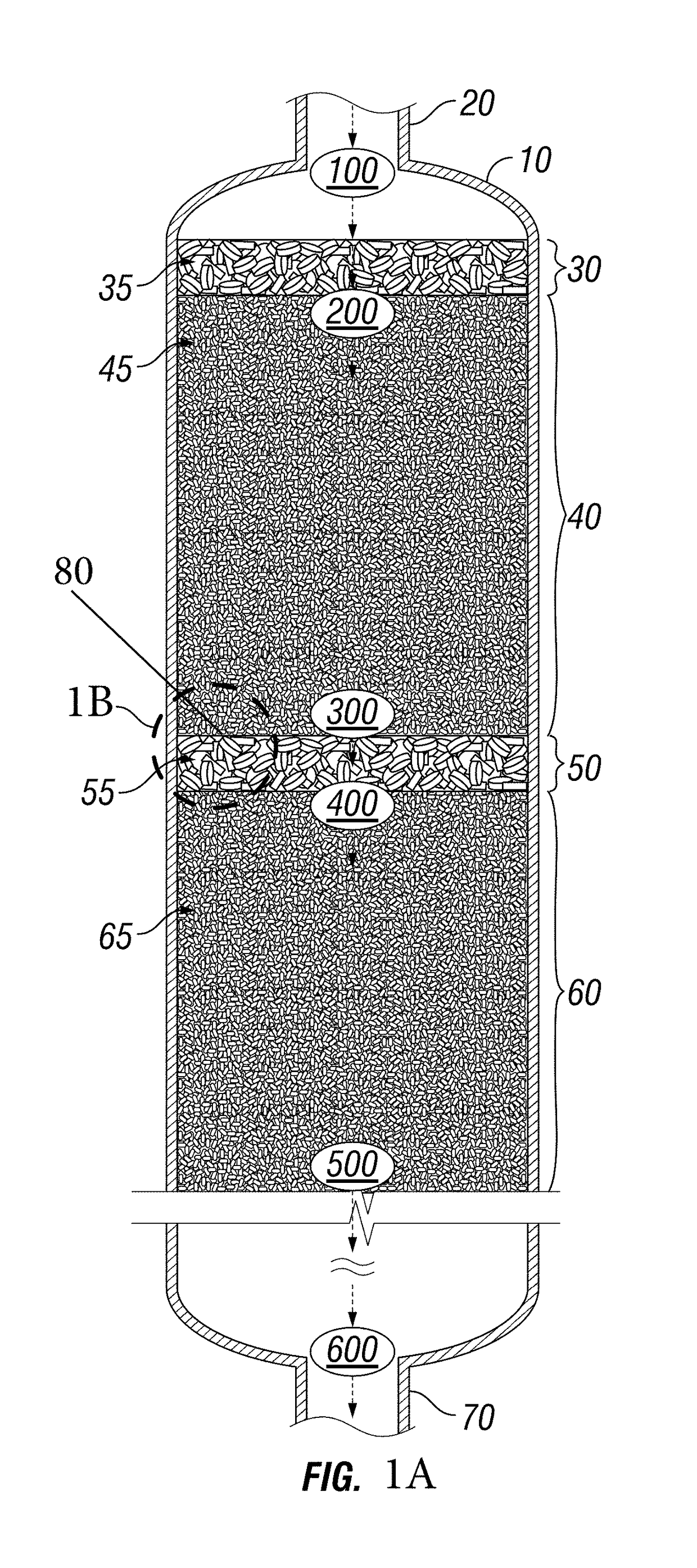
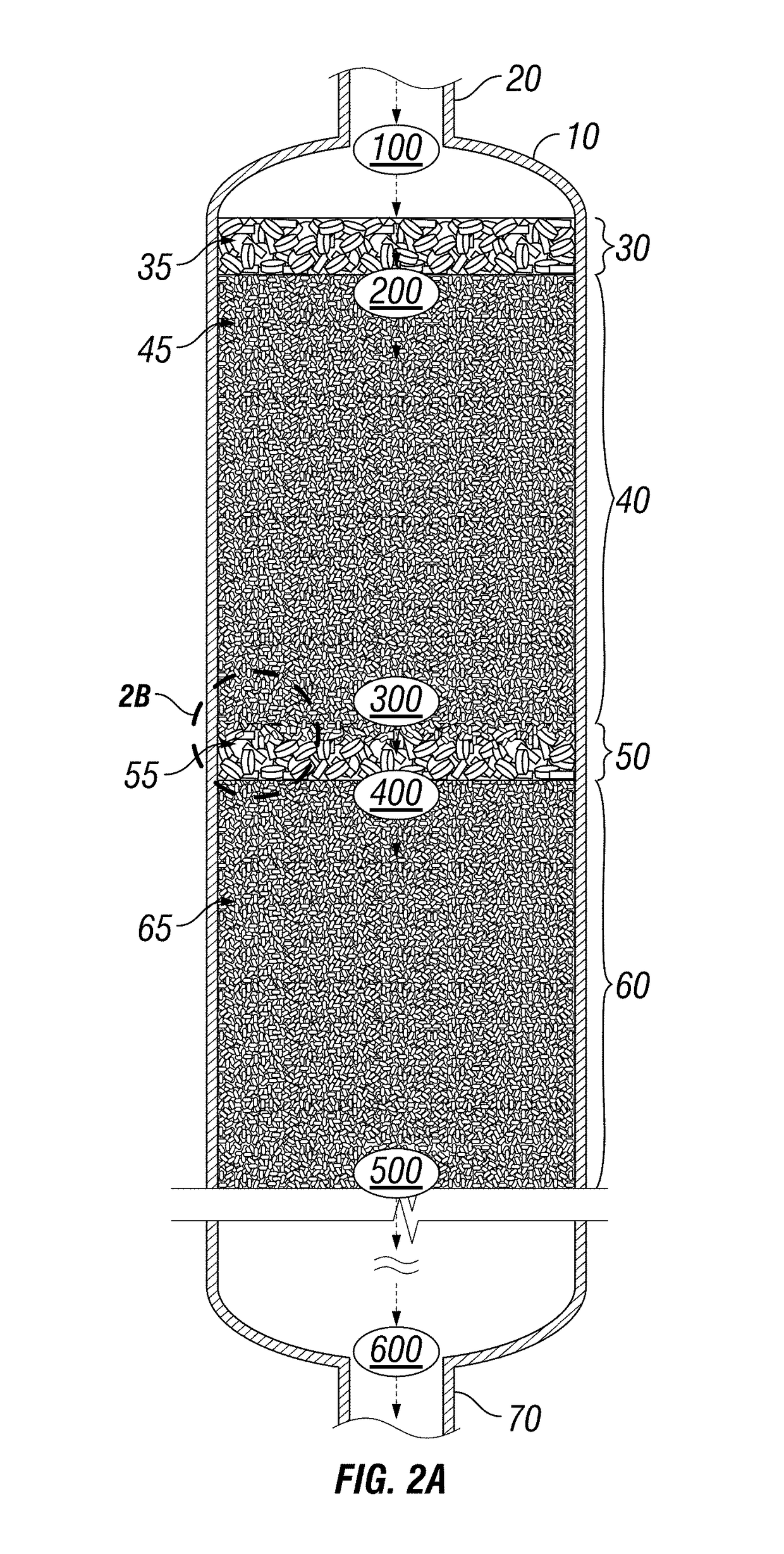
[0030]In accordance with the presently disclosed subject matter, various illustrative embodiments of methods for facilitating the redistribution and lateral redispersion of the flow of one or more streams within bed vessels are provided.

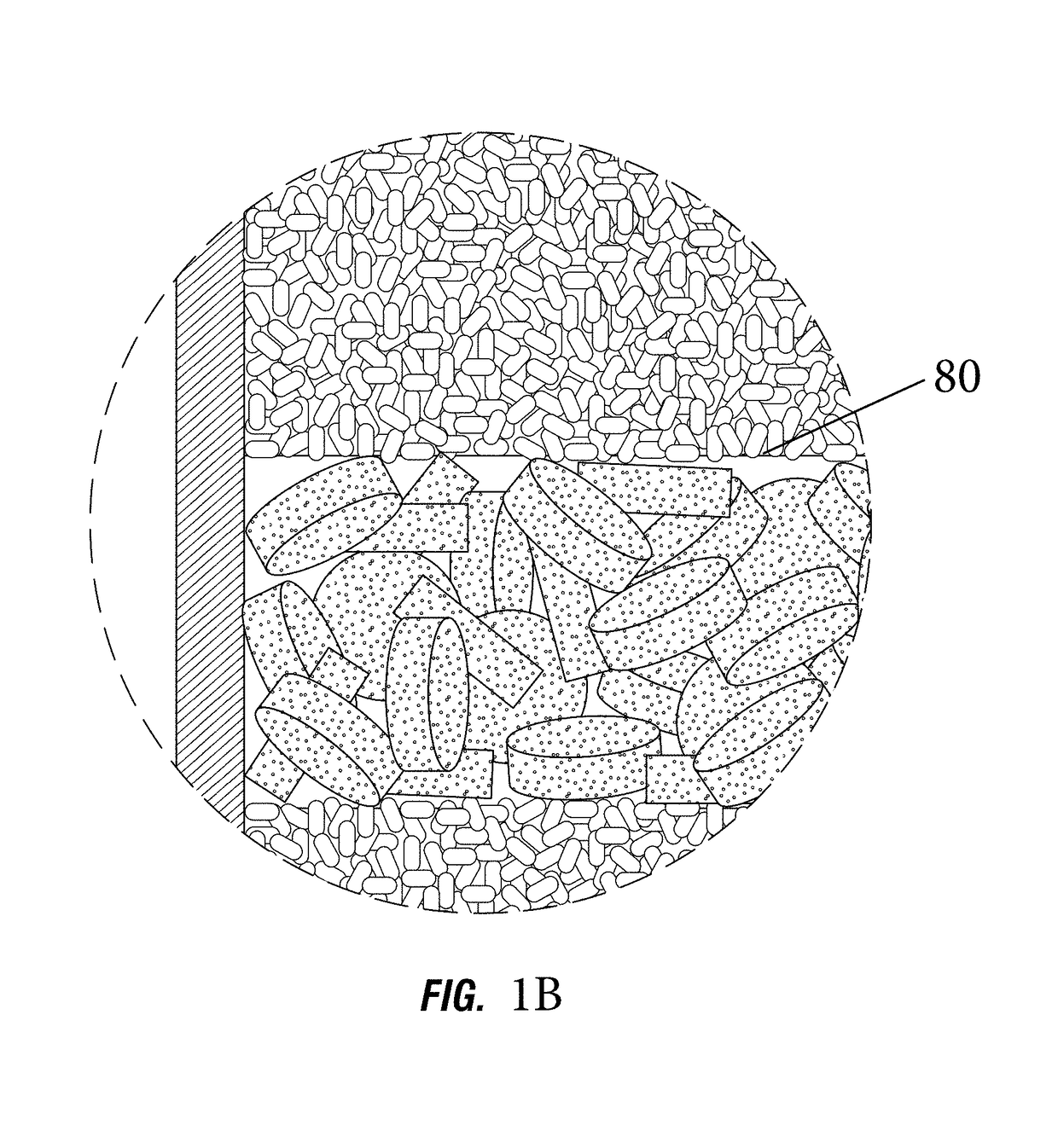
[0031]The concept of “redistribution” as described in the presently disclosed subject matter concerns the division and dispersion of process streams across and throughout the internals contained within a bed vessel. Such division and dispersion is facilitated by redistribution treating zones disposed to counter negative stream coalescing effects which cause stream channeling and which, at best, prevent achievement of the designed performance of the processing zones installed within the bed vessel and, at worst, cause unsafe operating circumstances which increase operating risk.

[0032]In certain illustrative embodiments, disposed within such bed vessels are internal materials and structures as well as multiple operating zones. One type of operating zon...


PUM


Abstract

A method for facilitating the distribution of the flow of one or more streams within a bed vessel is provided. Disposed within the bed vessel are internal materials and structures including multiple operating zones. One type of operating zone can be a processing zone composed of one or more beds of solid processing material. Another type of operating zone can be a treating zone. Treating zones can facilitate the distribution of the one or more streams fed to processing zones. The distribution can facilitate contact between the feed streams and the processing materials contained in the processing zones.

Description

RELATED APPLICATIONS[0001]This application claims the benefit, and priority benefit, of U.S. Provisional Patent Application Ser. No. 62 / 314,069, filed Mar. 28, 2016 and U.S. Provisional Patent Application Ser. No. 62 / 294,768, filed Feb. 12, 2016, the contents of each of which are incorporated by reference herein in their entirety.BACKGROUND[0002]Field of the Invention[0003]The presently disclosed subject matter relates to facilitating the flow of streams within vessels utilized in the process industry.[0004]Description of Related Art[0005]The number of bed vessels installed and operating in industry totals in the tens of thousands worldwide. Bed vessels are usually large with diameters ranging from 4 to 18 feet and heights from 10 to over 100 feet. The volume of such bed vessels is substantially filled with bed vessel internals. Each year, the number of bed vessels that are shutdown or are constructed and commissioned totals in the hundreds. The designed lifetime of these bed vessel...

Claims


Application Information

Patent Timeline
IPC IPC(8): B01J8/12B01J8/18F15D1/00
CPCF15D1/00B01J19/30B01J8/0453B01J2208/0084B01J2208/00938B01J2208/025B01J2219/30207B01J2219/30211B01J2219/30296B01J2219/30416B01J2219/315B01J8/04
Inventor GLOVER, JOHN N.HAM, PETER GREGORYSCHNEIDER, AUSTIN
Owner CRYSTAPHASE PRODS
Learn More