Bearing and bearing arrangement

a bearing arrangement and bearing technology, applied in the direction of roller bearings, mechanical energy handling, mechanical apparatus, etc., can solve problems such as misalignment ability, and achieve the effect of adaptability and usefulness

Active Publication Date: 2017-08-15
AB SKF
View PDF18 Cites 0 Cited by
  • Summary
  • Abstract
  • Description
  • Claims
  • Application Information

AI Technical Summary

Benefits of technology

[0005]In view of the above, an object of the present invention is to provide a new spherical roller bearing design and bearing arrangement which alleviates at least some of the drawbacks of the prior art. Moreover, an object of the present invention is to provide a spherical roller bearing design which is more adaptable and useful for applications where there are axial loads acting on the bearing.
[0009]With this design, where the cage will center on the roller elements and essentially in the pitch circle diameter of the bearing, a more robust bearing will be realized for applications where there is an axial load acting on the bearing. In a further embodiment, the essentially in-pitch roller centering is arranged such that one of the first or second roller rows is in contact with the cage. More specifically, it will be the roller row which is loaded by the axial load acting on the bearing. This will lead to that the cage will behave in a more stable manner in the bearing since it centers on the loaded roller row. The rollers of this roller row will be fixed in its specific roller path in the bearing and may not fluctuate or skew due to that these rollers are loaded. The other roller row, which is thus unloaded, will be transported and guided by the cage which moves in a stable manner.
[0010]In an embodiment of the present invention, the cage pockets in relation to the roller elements contained therein present a specific gap in the tangential direction of the cage, and wherein the tangential gap is set such that the cage pockets of one of the roller rows will contact the roller elements of the one roller row when an axial force is applied to the bearing. Thus, by setting the tangential gap such that there will be a contact between the roller elements in one of the roller rows when there is an axial force acting on the bearing, the cage will be centered by the rollers. In addition, the shape of the cage pocket and the tangential gap may be set such that the cage is essentially in-pitch centered, i.e. the contact cage / rollers will be in the vicinity of the bearing's pitch circle diameter (PCD), which will lead to a more stable roller centering.
[0011]In an embodiment of the present invention, the bearing does not present any spacer ring or mid-flange axially in-between the first and second roller rows. It is well known to make use of a spacer ring, such as a guide ring axially in-between the two roller rows of the bearing. The guide ring is especially useful when the bearing is used in more high-speed applications. In addition, the cage is often centered on the guide ring, which in turn is in contact with the inner ring. By removing the guide ring from the bearing, there will be fewer components. This is of course advantageous in terms of cost, but also it may lead to a more robust bearing design due to the fact that there will be fewer components in the bearing. Moreover, a mid-flange, which is frequently used in prior art designs, is also costly to have since the manufacturing of an inner ring comprising a mid-flange will be more complicated. Also, the presence of a mid-flange will result in more material, leading to a higher weight and also a higher material cost. In addition, the design of the present invention will lead to that there will be a free space between the cage and the inner ring in-between the first and second roller row. This space can be used for lubricant, such as grease or oil. This may lead to that the lubrication of the contact between the raceways of the inner ring and the roller elements is improved since the lubricant can be stored in the proximity of these contact zones.
[0013]In an embodiment of the present invention, a spherical roller bearing is presented, wherein at least one of the plurality of cage pockets is radially outwardly enclosing the roller contained therein such that the roller element will be restricted to move radially outwardly out from the at least one cage pocket. By having such a design the roller elements can be prevented from falling out from the bearing, for instance during assembly of the bearing. In another embodiment, the inner ring further presents a first and second axially outer region on opposite axial sides of the bearing, wherein the respective first and second axially outer region presents a first and second respective side flange. The side flange can further improve and prevent rollers from falling out from the bearing.
[0017]According to the third aspect of the invention, a wind turbine bearing arrangement is presented, wherein the wind turbine bearing arrangement comprises a main shaft and at least one bearing for supporting the main shaft, wherein the at least one bearing will accommodate a force in its axial direction, and wherein the bearing is a bearing according to any embodiment of the first aspect of the invention. It shall be noted that any embodiment of the third aspect of the invention is applicable to any embodiment of the first and second aspect of the invention and vice versa. In wind turbine applications, there is often an axial force acting on one of the bearing's in the arrangement. A bearing according to the first aspect of the invention would therefore be advantageously used in this kind of application. In addition, the rotating speed of a wind turbine bearing arrangement is relatively low. In one of the embodiments of the bearing, when there is no spacer ring (such as a guide ring) or mid-flange, would also be another good alternative since the need for a guide ring or mid-flange may not be necessary due to the low rotating speeds.

Problems solved by technology

Spherical roller bearings are well known for its ability to accommodate radial and axial loads, but also for its misalignment ability.

Method used


Image

  • Bearing and bearing arrangement
  • Bearing and bearing arrangement
  • Bearing and bearing arrangement

Examples


Embodiment Construction

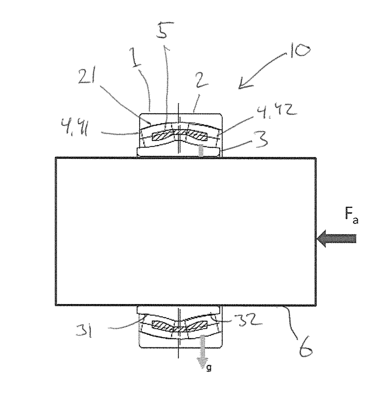
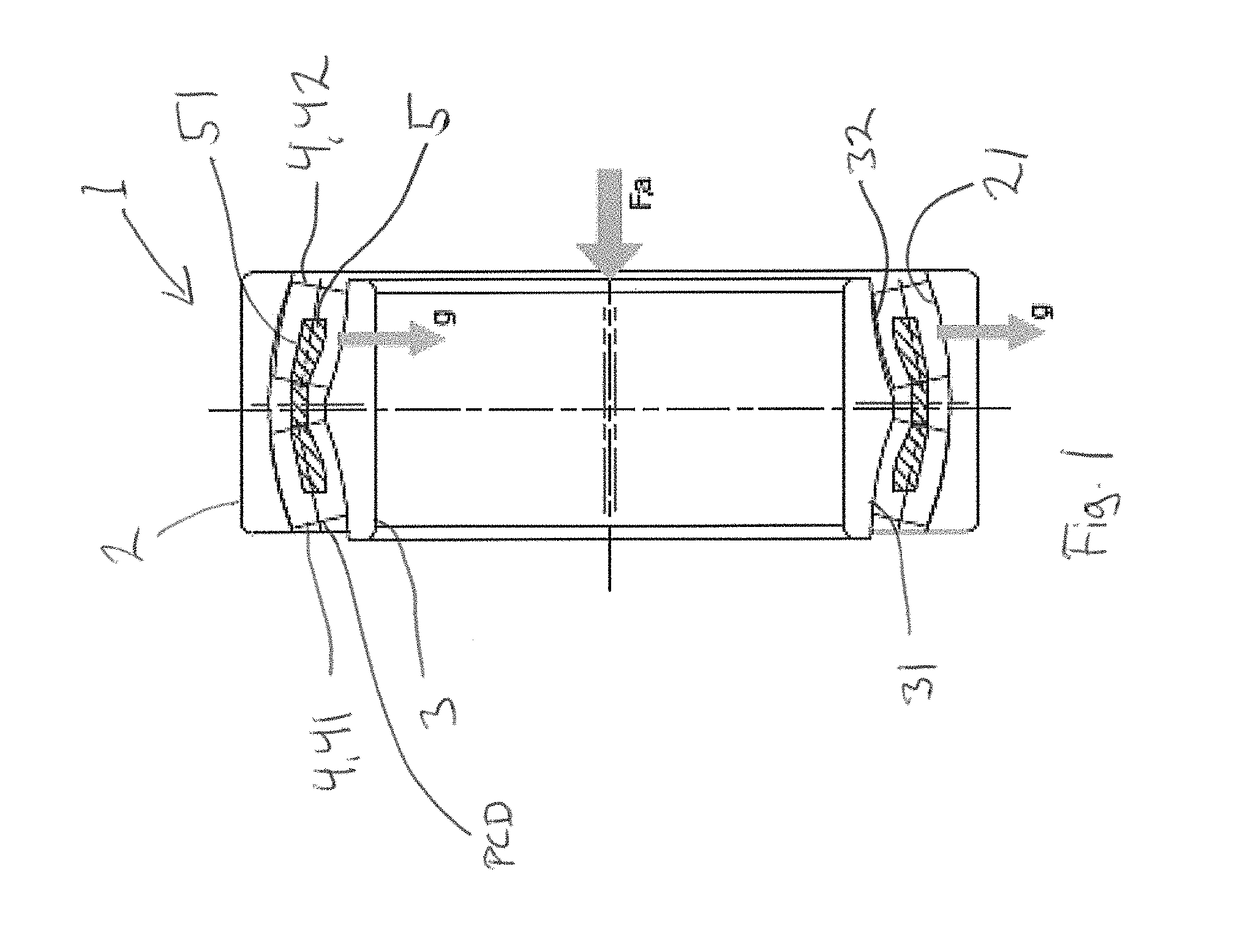
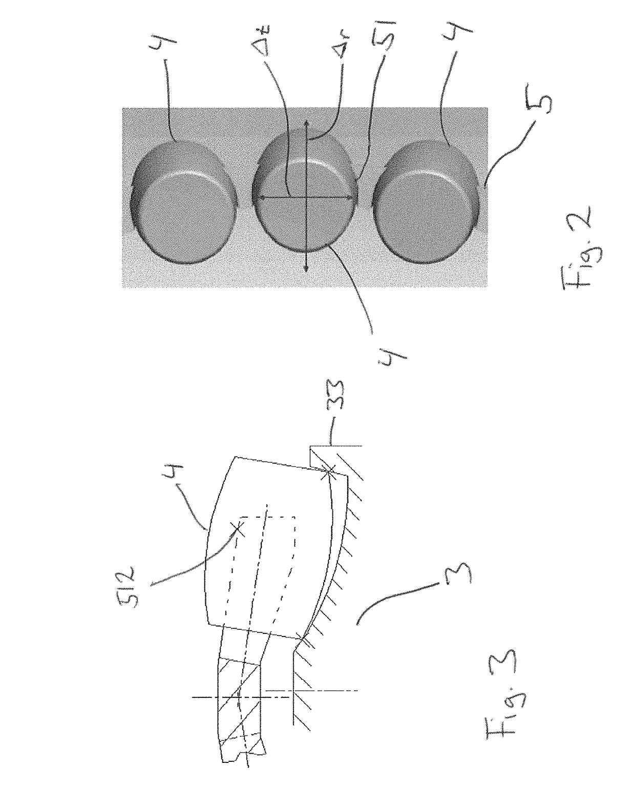
[0026]FIG. 1 shows an embodiment of a spherical roller bearing 1 according to the present invention. The bearing 1 comprises an outer ring 2 presenting at least one inner raceway 21, an inner ring 3 presenting a first and a second outer raceway 31, 32, and a plurality of roller elements 4 arranged in a first and second roller row 41, 42 in-between the at least one inner raceway 21 and the respective first and second outer raceway 31, 32. In addition, the bearing 1 comprises a cage 5 for guiding and / or retaining the roller elements 4 in the first and second roller row 41, 42, and wherein the cage 5 presents a plurality of cage pockets 51, in which each cage pocket 51 one of the roller elements 4 is located. The bearing 1 further presents a specific pitch circle diameter PCD, and the cage 5 is essentially in-pitch roller centered in relation to the pitch circle diameter PCD when there is an axial force acting on the bearing 1. In addition, in this embodiment, there is no guide ring or...


PUM


Abstract

A spherical roller bearing having an outer ring providing at least one inner raceway, an inner ring providing a first and a second outer raceway, a plurality of roller elements arranged in a first and second roller row in-between the at least one inner raceway and the respective first and second outer raceway is provided. The bearing provides a cage for guiding the roller elements in the first and second roller row, the cage includes a plurality of cage pockets, wherein in each cage pocket one of the roller elements is disposed. The bearing further presents a specific pitch circle diameter (PCD), and the cage is essentially in-pitch roller centered in relation to the pitch circle diameter (PCD) when there is an axial force acting on the bearing. In addition, the present invention regards a bearing arrangement and a wind turbine bearing arrangement.

Description

CROSS-REFERENCE TO RELATED APPLICATIONS[0001]This application claims priority to Swedish patent application no. 1550422-8 filed on Apr. 9, 2015, the contents of which are fully incorporated herein by reference.TECHNICAL FIELD[0002]According to a first aspect, the invention regards a spherical roller bearing. According to a second aspect, the invention regards a bearing arrangement. According to a third aspect, the invention regards a wind turbine bearing arrangement.BACKGROUND[0003]Spherical roller bearings are well known for its ability to accommodate radial and axial loads, but also for its misalignment ability. These bearings are used in many different applications, especially in more demanding applications where there are larger loads and also where there may be shaft deflections. One example of where a spherical roller bearing can be advantageously used is in wind turbine applications. Other examples of areas where these bearings can be a suitable alternative is in pulp and pap...

Claims


Application Information

Patent Timeline
Patent Type & Authority Patents(United States)
IPC IPC(8): F16C19/38F16C33/30H02K7/08F16C23/08F16C33/66F16C33/58F16C33/49F16C33/50F16C33/48
CPCF16C23/086F16C33/48F16C33/495F16C33/504F16C33/583F16C19/38F16C2300/14F16C2360/31H02K7/08F16C23/082F16C33/4623F16C33/58F16C2240/80
Inventor LOOF, MARCUSJAMES, PETERSTIGSJOO, LARS
Owner AB SKF
Why Eureka
Try Eureka