Route planning

a technology for determining routes and routes, applied in the direction of process and machine control, navigation instruments, instruments, etc., can solve the problems of repetitive or time-consuming tasks, algorithms for determining paths or routes for vehicles tend to not be capable of determining routes, etc., and achieve the effect of reducing the likelihood of a failure of determined routes

Active Publication Date: 2017-08-15
BAE SYSTEMS PLC
View PDF8 Cites 3 Cited by
  • Summary
  • Abstract
  • Description
  • Claims
  • Application Information

AI Technical Summary

Benefits of technology

[0007]The present inventor has realised that, by planning routes for multi-vehicle rendezvous such that localisation uncertainty of multiple vehicles is accounted for, a likelihood of a failure of the determined routes tends to be reduced.

Problems solved by technology

Autonomous vehicles are often used to conduct dangerous, repetitive or time consuming tasks.
Many conventional algorithms for determining paths or routes for vehicles tend not to be capable of determining routes that provide multi-vehicle rendezvous.

Method used


Image

  • Route planning
  • Route planning
  • Route planning

Examples


Embodiment Construction

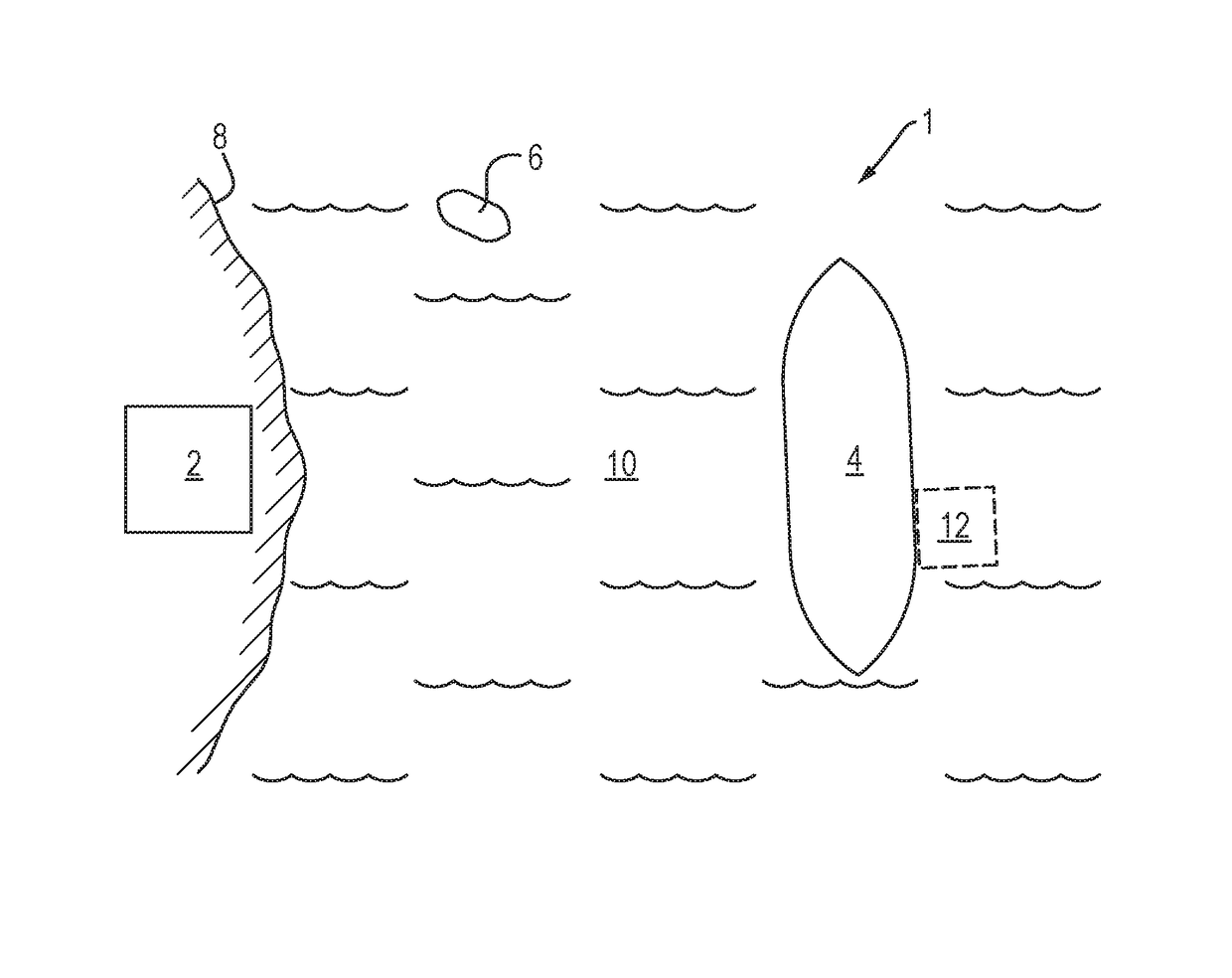
[0036]FIG. 1 is a schematic illustration (not to scale) of a scenario 1 in which an embodiment of a method of controlling a group of vehicles is to be implemented.

[0037]The scenario 1 comprises a ground station 2, a first vehicle 4, and a second vehicle 6.

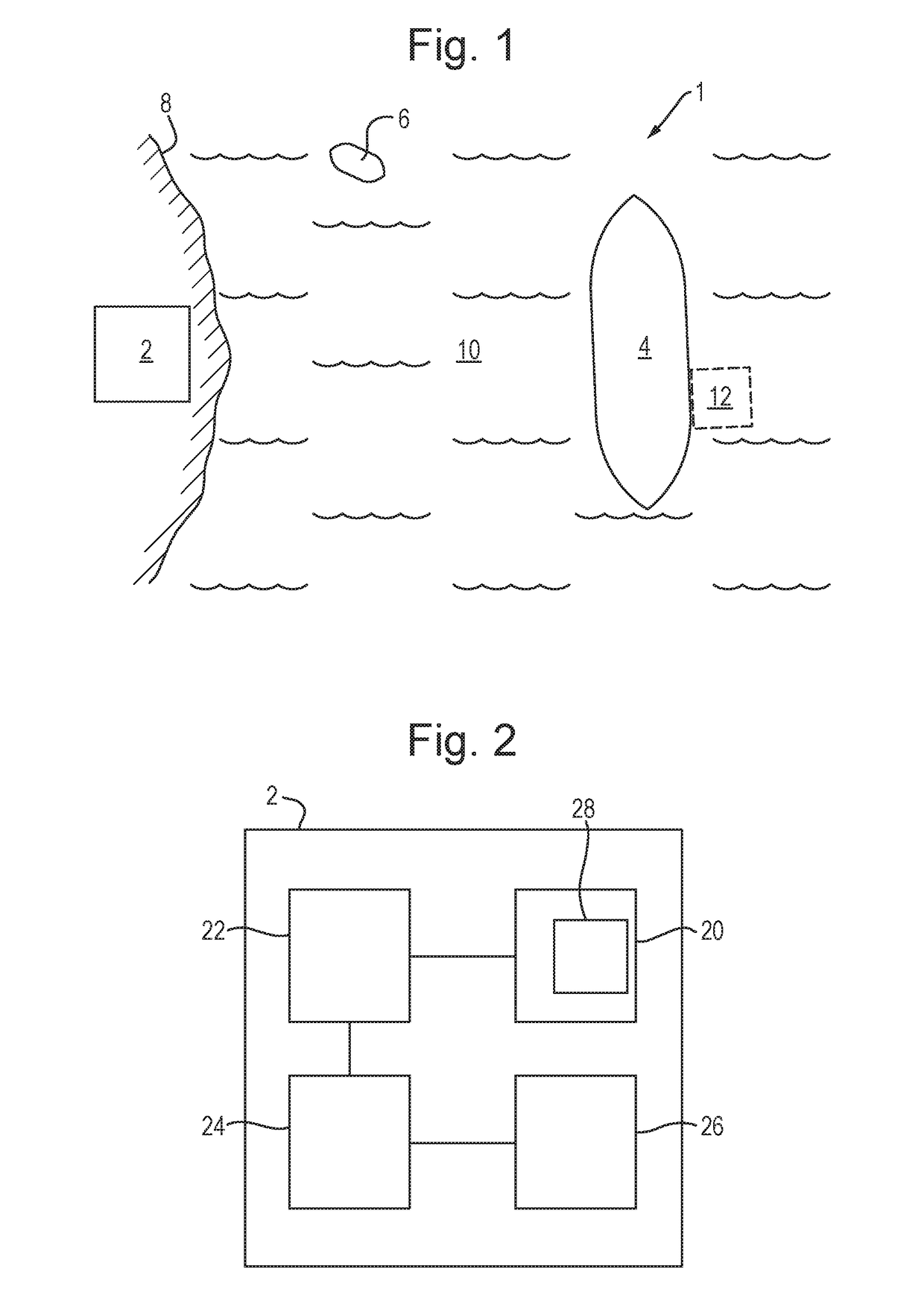
[0038]In the scenario 1, the ground station 2 is located on land 8 that is adjacent to a body of water 10 (e.g. a sea). The ground station is described in more detail later below with reference to FIG. 2.

[0039]In the scenario 1, the first vehicle 4 is a water-based vehicle. In particular, the first vehicle 4 is an unmanned autonomous ship which is controllable by the ground station 2 as described in more detail later below with reference to FIGS. 3 to 10. The first vehicle 4 is located at the surface of the body of water 10 at a position that is remote from the land 8.

[0040]In the scenario 1, the second vehicle 6 is a water-based vehicle. In particular, the second vehicle 6 is an unmanned autonomous boat. In this scenario 1, the se...


PUM


Abstract

A method and apparatus for determining a route for a vehicle (6), the method comprising: measuring a position of the vehicle (6); providing a specification of a region (12) into which the vehicle (6) is to be moved; and, using the measurements and specification, determining the vehicle route. The route determination process comprises constructing a graph (34) within a state space (X) of the vehicle (6), identifying, within the graph (34), a path for the vehicle (6), performing a path shortening algorithm on the identified path, and, using the shortened path, determining the vehicle route. The path shortening algorithm comprises: selecting two vertices along the path that are separated by at least two edges; connecting the two selected vertices with an additional edge; and, depending on certain cost values, removing the edges and vertices by which the selected vertices are connected, and including, in the path, the additional edge.

Description

FIELD OF THE INVENTION[0001]The present invention relates to determining routes for vehicles.BACKGROUND[0002]Autonomous vehicles are often used to conduct dangerous, repetitive or time consuming tasks.[0003]Multiple interacting autonomous vehicles may be used to achieve a common goal.[0004]During certain tasks it may be desired or necessary that two or more of the autonomous vehicles “rendezvous” i.e. move in such a way that one autonomous vehicle is located within a region that has a fixed location relative to a different autonomous vehicle. A rendezvous between two of more vehicles may be, for example, for the purpose of a transfer of fuel or cargo between the autonomous vehicles, transportation of one autonomous vehicle by another, or the undertaking of repairs.[0005]Many conventional algorithms for determining paths or routes for vehicles tend not to be capable of determining routes that provide multi-vehicle rendezvous.SUMMARY OF THE INVENTION[0006]The present inventor has real...

Claims


Application Information

Patent Timeline
Patent Type & Authority Patents(United States)
IPC IPC(8): B60L3/00G01C21/20G05D1/02G05D1/00G01C21/34G06F7/00
CPCG01C21/20G01C21/3438G05D1/0206G05D1/0291
Inventor SIMPSON, RICHARD EDWARD
Owner BAE SYSTEMS PLC
Why Eureka
Try Eureka