Burst-mode operation of a switching converter

a technology of switching converter and burst mode, which is applied in the direction of electric variable regulation, process and machine control, instruments, etc., can solve the problems of modern controllers entering burst mode, problems may occur, and low load consumption

Active Publication Date: 2017-08-15
INFINEON TECH AG
View PDF16 Cites 0 Cited by
  • Summary
  • Abstract
  • Description
  • Claims
  • Application Information

AI Technical Summary

Benefits of technology

[0098]Although various exemplary embodiments of the invention have been disclosed, it will be apparent to those skilled in the art that various changes and modifications can be made which will achieve some of the advantages of the invention without departing from the spirit and scope of the invention. It will be obvious to those reasonably skilled in the art that other components performing the same functions may be suitably substituted. It should be mentioned that features explained with reference to a specific figure may be combined with features of other figures, even in those cases in which this has not explicitly been mentioned. Further, the methods of the invention may be achieved in either all software implementations, using the appropriate processor instructions, or in hybrid implementations that utilize a combination of hardware logic and software logic to achieve the same results. Such modifications to the inventive concept are intended to be covered by the appended claims.

Problems solved by technology

Under low-load conditions, which is when a power consumption of the load is very low, modern controllers enter a burst mode.
Problems may occur when the burst frequency is in a frequency range of between 1 kHz and 4 kHz.
A burst frequency in this range may cause an annoying audible noise.

Method used


Image

  • Burst-mode operation of a switching converter
  • Burst-mode operation of a switching converter
  • Burst-mode operation of a switching converter

Examples


Embodiment Construction

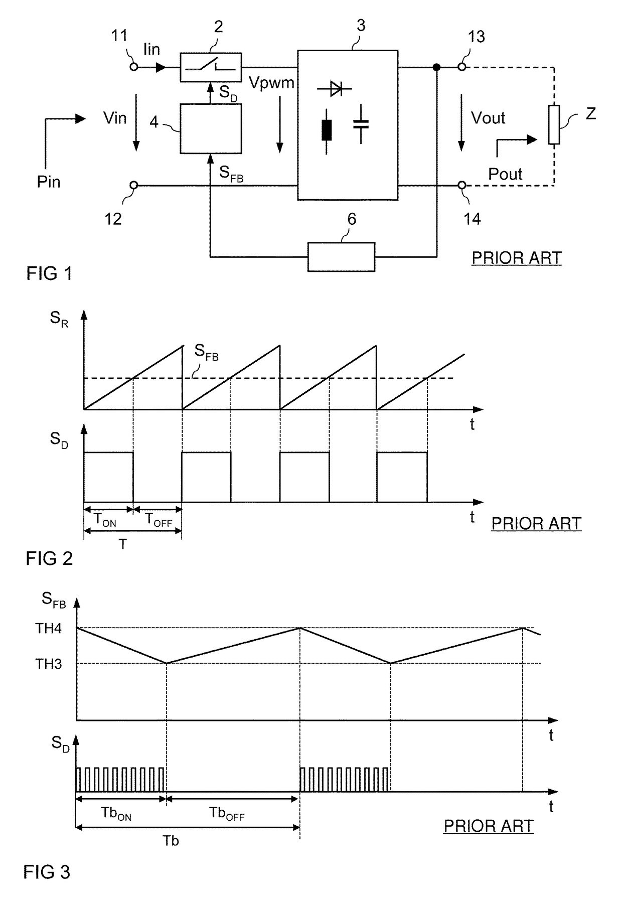
[0025]FIG. 1 illustrates a basic block diagram of a switching converter. The switching converter includes input terminals 11, 12 for applying an input voltage Vin, and output terminals 13, 14 for providing an output voltage Vout. The output voltage Vout can be supplied to a load Z (illustrated in dashed lines). The switching converter includes at least one switching element 2 that is connected between one of the input terminals 11, 12 and a rectifier arrangement 3. In the embodiment illustrated in FIG. 1, the switching element 2 is connected between a first input terminal 11 and the rectifier arrangement. However, this is only an example. The switching element 2 could also be connected between a second input terminal 12 and the rectifier arrangement 3. The input voltage Vin can be a DC voltage or an AC voltage.

[0026]The switching element 2 is switched on and off in accordance with a drive signal SD provided by a controller 4. By virtue of being switched on and off the switching elem...


PUM


Abstract

In accordance with an embodiment, a method of driving a switching element in a switching converter includes generating a feedback signal that is dependent on the output voltage, driving the switching element in a plurality of subsequent burst cycles, determining a burst frequency, and adjusting an effective switching frequency in at least one burst cycle dependent on the determined burst frequency. Each burst cycle includes a burst-on period and a subsequent burst-off period, and determining the burst frequency includes evaluating a duration of at least one burst cycle.

Description

TECHNICAL FIELD[0001]Embodiments of the present invention relate to a switching converter. The invention, in particular, relates to a method for operating a switching converter in a burst mode and to a switching converter configured to be operated in a burst mode.BACKGROUND[0002]Switching converters are widely used in the field of power conversion. A switching converter includes at least one switch that is configured to generate a pulse-width modulated (PWM) voltage from an input voltage, and a rectifier arrangement that receives the PWM voltage and generates an output voltage to be supplied to a load. Usually the rectifier arrangement includes at least one inductive storage element, such as a choke, and at least one capacitive storage element, such as a capacitor. The PWM voltage is generated by switching the switching element on and off in accordance with a PWM drive signal. The drive signal is provided by a controller dependent on the output voltage. The controller is configured ...

Claims


Application Information

Patent Timeline
Patent Type & Authority Patents(United States)
IPC IPC(8): H02M3/156H02M3/335H02M1/00
CPCH02M3/156H02M3/33507H02M2001/0035Y02B70/16H02M1/0035Y02B70/10
Inventor KOK, SIU KAMMAO, MINGPINGGONG, XIAOWU
Owner INFINEON TECH AG
Why Eureka
Try Eureka