Pressurizable fluid container apparatus

a fluid container and pressurized technology, applied in the field of fluid containers, can solve the problems of screw-type caps or pop-on/pop-off lids, damage to the seal, pull-valves, etc., and achieve the effect of increasing the structural integrity of the relief tube extension and improving the outflow of liquid

Active Publication Date: 2017-08-29
LUNATEC
View PDF21 Cites 10 Cited by
  • Summary
  • Abstract
  • Description
  • Claims
  • Application Information

AI Technical Summary

Benefits of technology

[0018]In one embodiment of the present invention, an uptake adapter may be inserted between the relief tube and the relief tube extension to improve the outflow of liquid and increase the structural integrity of the relief tube extension.

Problems solved by technology

Depending on the type of fluid dispensing system, constant or frequent use of fluid containing devices and bottles can lead to damage to, for example, the pull-valve, or loss of a screw-type cap or pop-on / pop-off lid.
Furthermore, for squeeze-type containers, the frequent deformation of the container can lead to structural failure of the walls of the container.
Additionally, the ability to control water flow to clean or wash can be difficult as the fluid dispensing device must be tilted at a particular angle and / or squeezed to initiate the flow of water.
Additionally, transmission of germs and the inclusion of foreign material into the fluid becomes an increased risk from the constant and repetitive touching of the mouth to the pull-valve or rim and / or the repetitive opening of the container, exposing the contents to the environment.
Furthermore, the mechanical stress of repetitive opening and, in some cases, squeezing the bottle, may result in damaged or lost parts and a shortened product life span.

Method used


Image

  • Pressurizable fluid container apparatus
  • Pressurizable fluid container apparatus
  • Pressurizable fluid container apparatus

Examples


Embodiment Construction

[0032]Various embodiments or examples may be implemented in numerous ways, including as a system, a process, or an apparatus. A detailed description of one or more examples is provided below along with the accompanying figures. The detailed description is provided in connection with such examples, but is not limited to any particular example. The scope is limited only by the claims and numerous alternatives, modifications, and equivalents are encompassed. Numerous specific details are set forth in the following description in order to provide a thorough understanding. These details are provided for the purpose of example and the described techniques may be practiced according to the claims without some or all of these specific details. For clarity, technical material that is known in the technical fields related to the examples has not been described in detail to avoid unnecessarily obscuring the description.

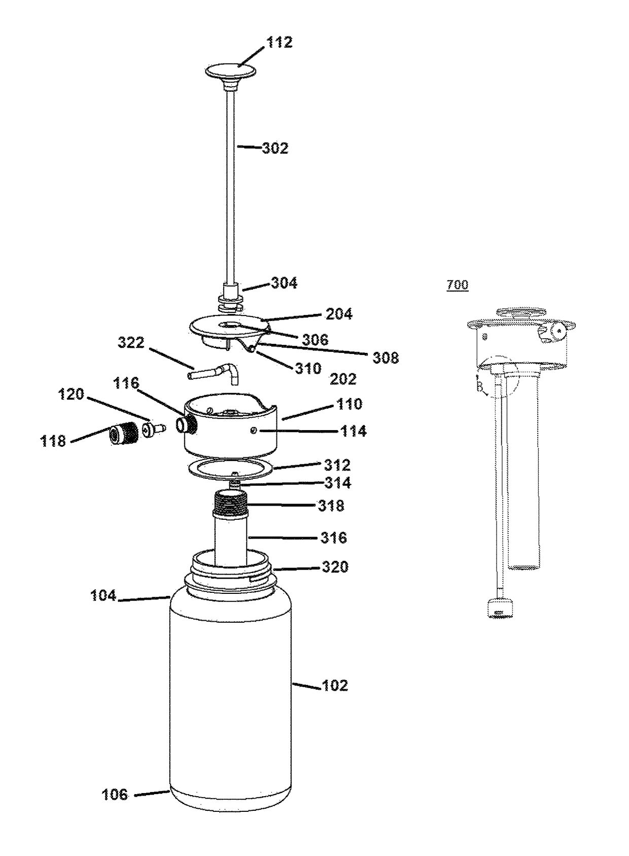
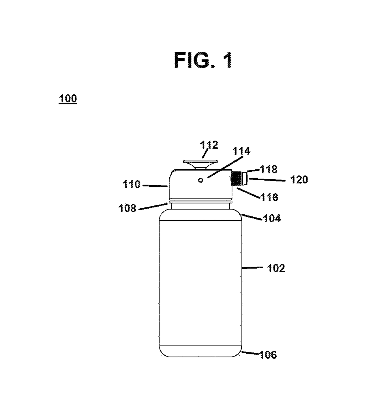
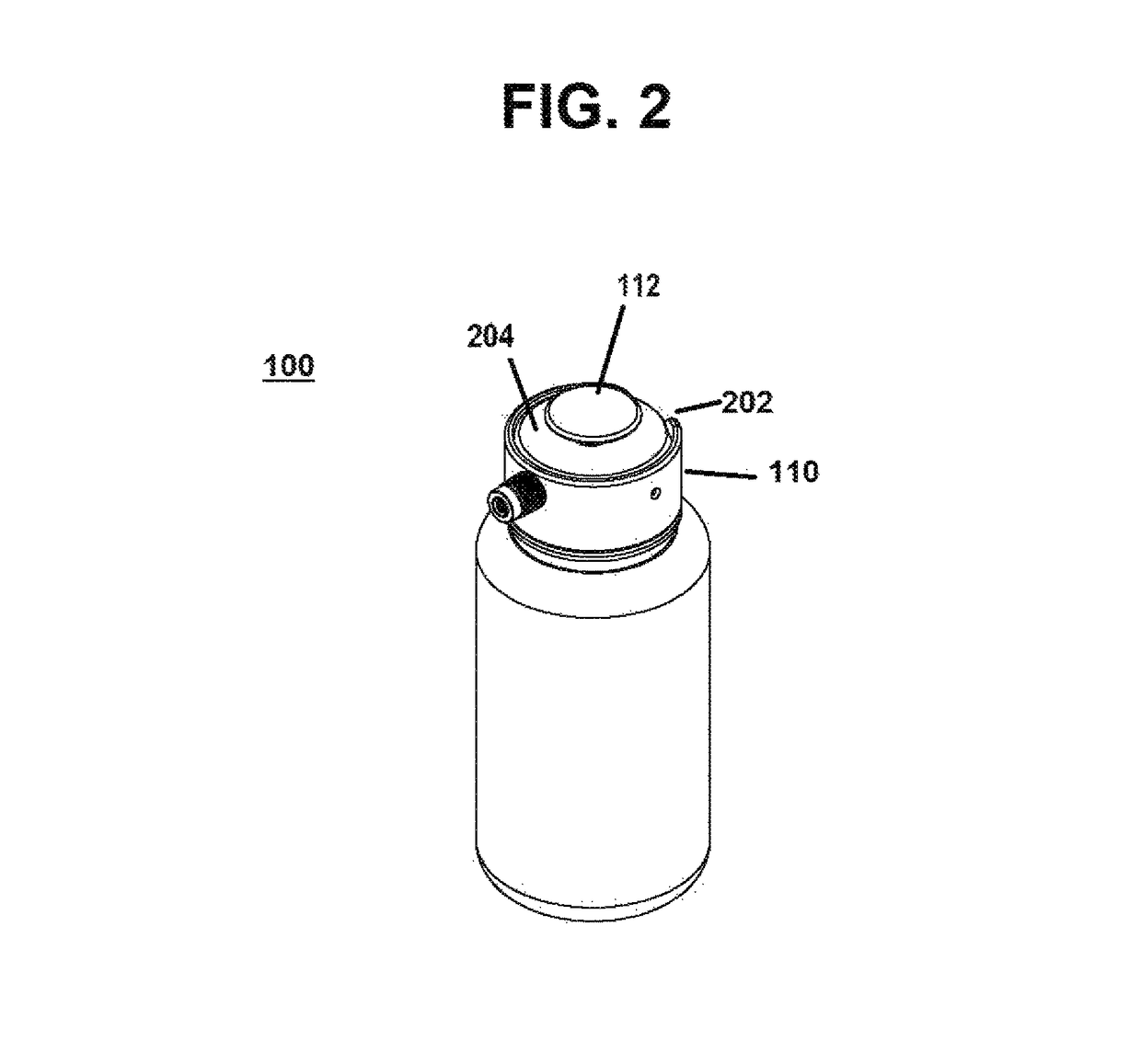
[0033]Referring now to FIG. 1, bottle assembly 100 includes body 102, it ma...


PUM


Abstract

A bottle cap assembly for pressurizing a water bottle is described herein. The bottle cap assembly comprises a cap, a teeter valve coupled to the top of the cap, a pressurizing plunger, a hollow pump shaft receiving the plunger, a hollow uptake adapter, a relief tube extension and a flexible conduit.

Description

FIELD OF THE INVENTION[0001]The present invention relates generally to the field of fluid containers, in which the bottle must be squeezed or tilted to release the flow of fluid to allow for ease of drinking, washing, and / or cleaning and is particularly applicable to sports bottles, or the like.BACKGROUND OF THE INVENTION[0002]In recent years, the number of health-conscious individuals has grown tremendously. In addition, research into the importance of clean water for hydration and other uses during health-improving activities: walking, hiking, biking, camping, and other outdoor activities has led to an increased need for fluid delivery devices that can provide fluids through a secure and hygienic means. Conventional fluid delivery devices, such as water bottles, are useful for various purposes in activities such as athletic, outdoor, recreational, or other uses. Typically, such devices are designed for a user to carry water, electrolytic fluid replacement drinks, or any type of li...

Claims


Application Information

Patent Timeline
Patent Type & Authority Patents(United States)
IPC IPC(8): B65D83/14B05B9/04B05B9/08B05B11/00B05B1/12B65D83/20
CPCB05B9/0827B05B9/0816B05B1/12B05B11/3061B05B11/3063B65D83/206B05B11/1061B05B11/1063
Inventor RHEA, NICKYOUNG, ERIC
Owner LUNATEC
Why Eureka
Try Eureka