Pulsatile blood pump

a technology of pulsatile blood and pump, which is applied in the direction of heart stimulators, prostheses, therapy, etc., can solve the problems of inability to leave the current lvads in-situ and deactivation, and the current lvads do not provide a life-line to recovered patients, so as to improve the perfusion of patients' limbs, organs and/or tissues

Inactive Publication Date: 2014-12-02
NOTTINGHAM UNIV HOSPITALS NHS TRUST
View PDF19 Cites 5 Cited by
  • Summary
  • Abstract
  • Description
  • Claims
  • Application Information

AI Technical Summary

Benefits of technology

[0009]Thus, the outflow from the native heart may be augmented through the use of the blood pump of the present invention. The blood pump is surgically placed interpositionally within the aorta (i.e. the blood pump is implanted into the aorta by end-to-end anastomosis to replace a resected portion of the aorta). The cross-sectional area of the blood passageway through the blood pump is caused to contract due to the flow of fluid into and out of the fluid chamber between the tubular body and the flexible membrane of the blood pump. The blood pump may be used in the temporary or long-term treatment of patients suffering heart failure through intermittent or temporary continuous use when counter-pulsed with the natural heart. Additional embodiments can also be contemplated so as to reduce the workload required from the native heart, to augment coronary artery perfusion, and / or to treat other circulatory diseases by introducing such a blood pump into the peripheral circulation.
[0012]The second group of patients for whom the present invention would be particularly beneficial are patients needing long term chronic support. This group of patients will never recover cardiac function and will be maintained on medical therapies in the long term. The “healthier” of these are minimally supported with medical therapies but require more aggressive support intermittently; typically such patients would be admitted to hospital for one or two weeks respite and receive low doses of inotropes and diuretics which is sufficient to reduce ventricular overload, to restore end organ function and to promote a feeling of well being. Patients receiving more aggressive medical therapies need additional support in times of crisis and would be admitted to intensive care and aided with an IABP such as those of U.S. Pat. No. 6,210,318 and EP0192574. Patients with the worst prognosis may well find themselves on the heart transplant list. A small number of these patients will suffer failing health whilst on the transplant list and will need mechanical assist to bridge them to transplantation. The present invention promises to be a useful treatment modality in each of these scenarios. For the “healthier” patients, treatment may be augmented with the blood pump of the present invention, in addition to medical therapy to provide respite. Once installed, and for subsequent readmission, use of the present blood pump can be very quickly effected and will be fast acting. For patients on higher doses of medication in crisis, the present invention will allow speedier deployment and will allow the patient to be ambulatory and reduce the risk of infection posed by IABPs, as described further below. The present invention will greatly reduce the cost of bridge-to-transplantation by removing the need for an implanted VAD or the need for intensive care beds that would have been required if an external VAD were used.
[0019]The tubular body may be rigid or may be flexible. Advantageously, the tubular body comprises a flexible material. More advantageously, the tubular body comprises one or more non-stretch elements for preventing the tubular body from distending significantly when fluid flows into the fluid chamber. For example, the non-stretch elements may be non-stretch filaments having a spiral, axial or annular configuration with respect to the tubular body.
[0027]According to a third aspect of the present invention, there is provided a method for the treatment of heart failure in a patient. The method comprises: resecting a portion of a blood vessel of the patient; anastomosing a pulsatile blood pump of the first aspect into the resected blood vessel; providing a fluid conduit which extends percutaneously out of the patient from the port of the blood pump; and driving fluid along the fluid conduit alternately into and out of the fluid chamber of the blood pump, thereby enabling the blood pump to pump blood along the blood passageway.
[0033]According to a fourth aspect of the present invention, there is provided a method for augmenting the perfusion of a patient's limbs and / or organs and / or tissue. The method comprises: resecting a portion of a peripheral blood vessel of the patient; anastomosing a pulsatile blood pump of the first aspect into the resected blood vessel; providing a fluid conduit which extends percutaneously out of the patient from the port of the blood pump; and driving fluid along the fluid conduit alternately into and out of the fluid chamber of the blood pump, thereby enabling the blood pump to pump blood along the blood passageway.

Problems solved by technology

However, current mechanical LVADs do not incorporate one-way valves making it infeasible to leave them in-situ and deactivated due to significant retrograde flow through them once they have been inactivated.
Current LVADs therefore do not provide a life-line to recovered patients, and re-operation is necessary to implant an additional device if cardiac function declines once again.

Method used


Image

  • Pulsatile blood pump
  • Pulsatile blood pump
  • Pulsatile blood pump

Examples


Embodiment Construction

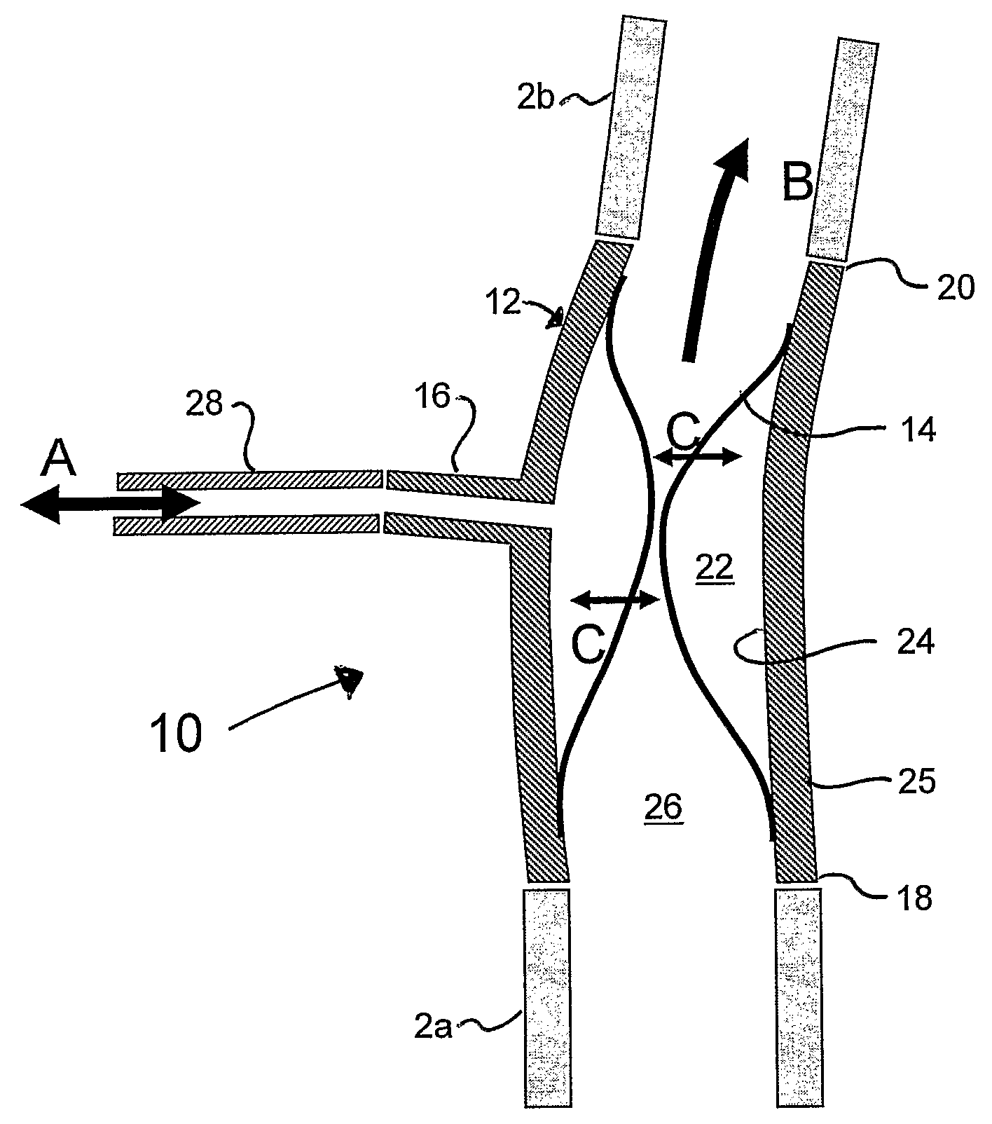
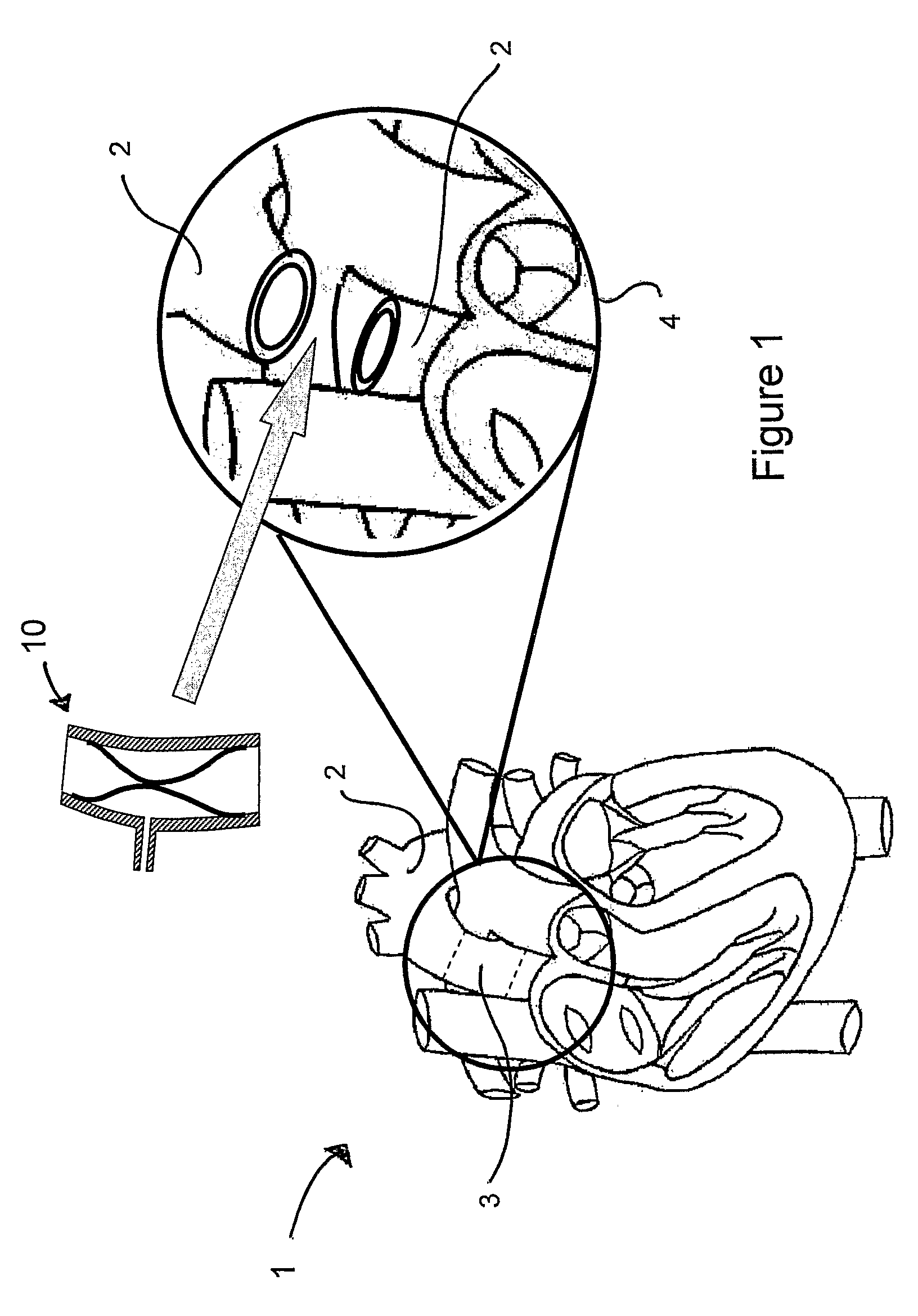
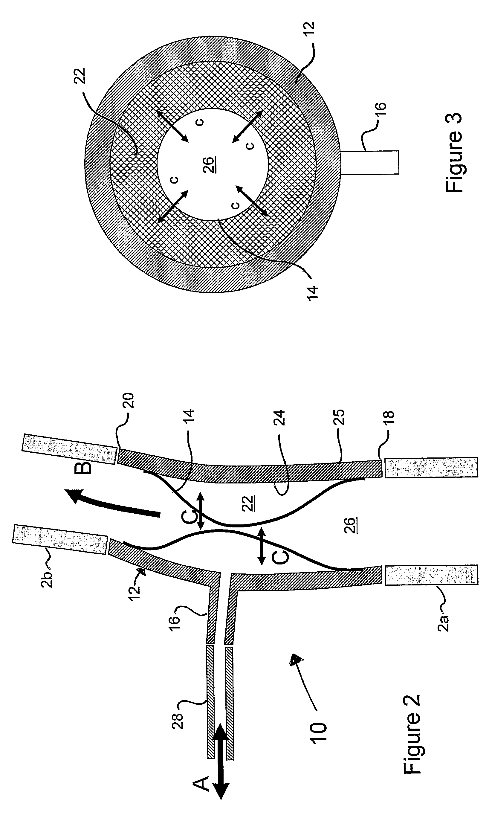
[0047]FIG. 1 shows a schematic representation of a human heart 1. A healthy heart 1 pumps blood to the body via the aorta 2. According to a preferred embodiment of the present invention, a portion 3 of the aorta 2 is resected, as shown in the enlarged view 4 of FIG. 1, and replaced by a pulsatile blood pump 10 placed interpositionally within the aorta 2 just distal of the aortic root and the remainder of the heart 1. The blood pump 10 may then be activated intermittently for short periods as required, or may be activated continuously for periods of limited duration. Therefore, this embodiment of the present invention provides a small pulsatile blood pump 10 having a volume of between 10 and 70 mL which may be permanently incorporated into the aorta 2 as an interpositional graft. In order to place the blood pump 10 in its desired position close to the heart 1, a section 3 of the aorta 2 must be removed. Thus, the blood pump 10 is positioned in the aorta 2 by end-to-end anastomosis (i...


PUM


Abstract

There is provided a pulsatile blood pump (10) for implantation into a patient. The pulsatile blood pump comprises a substantially tubular body (12) a flexible membrane (14) and a port (16). The substantially tubular body is for replacing a resected portion of a blood vessel of the patient. The substantially tubular body has first and second ends with a blood passageway extending therebetween for the passage of blood. The flexible membrane is attached to the tubular body so as to form a fluid chamber between the flexible membrane and an inner surface of the tubular body. The flexible membrane thereby separates the fluid chamber from the blood passageway. The tubular body comprises the port. The port is arranged to allow fluid to flow into and out of the fluid chamber such that the volume of the fluid chamber increases and the volume of the blood passageway decreases when fluid flows into the fluid chamber via the port, and such that the volume of the fluid chamber decreases and the volume of the blood passageway increases when fluid flows out of the fluid chamber via the port. The blood pump is thereby enabled to pump blood along the blood passageway.

Description

CROSS-REFERENCED TO RELATED APPLICATION(S)[0001]This application is a National Phase Patent Application of International Application Number PCT / GB2008 / 003309, filed on Sep. 29, 2008, which claims priority to and the benefit of GB Application No. 0718943.4, filed Sep. 28, 2007.FIELD OF THE INVENTION[0002]The present invention relates to a pulsatile blood pump for implantation into a patient. The invention also relates to a blood pump system incorporating such a pulsatile blood pump, and to a method for the treatment of heart failure in a patient.BACKGROUND OF THE INVENTION[0003]Heart failure is a major cause of death in the developed and developing world; it is estimated that there are currently 901,500 sufferers in the United Kingdom with 65,000 new cases added annually. The British Heart Foundation estimates the annual cost of heart failure is £625 million in the UK alone. In the United States, the corresponding statistics are 5,000,000 sufferers with 550,000 new cases annually and...

Claims


Application Information

Patent Timeline
Patent Type & Authority Patents(United States)
IPC IPC(8): A61M1/10A61M1/12A61N1/362
CPCA61M1/12A61M1/1086A61M1/1037A61M1/127A61M60/268A61M60/135A61M60/896A61M60/148A61M60/554A61M60/427A61M60/139A61M60/531
Inventor TANSLEY, GEOFFREY DOUGLASRICHENS, DAVID
Owner NOTTINGHAM UNIV HOSPITALS NHS TRUST
Why Eureka
Try Eureka