
Solenoid of electromagnetic valve

a solenoid and valve technology, applied in the direction of valve operating means/release devices, magnets, magnetic bodies, etc., can solve the problems of enameled wire breaking and becoming disconnected, the cross portion may be too narrow to function as a flow path, and the process becomes complicated

Active Publication Date: 2017-08-29
NIDEC TOSOK CORP
View PDF26 Cites 7 Cited by
  • Summary
  • Abstract
  • Description
  • Claims
  • Application Information

AI Technical Summary

Benefits of technology

[0006]Both end portions of the enameled wire wound around the bobbin extend to terminals for connecting with the outside, which are disposed on an outer side of one end of the bobbin, and are connected and fixed to the terminals. At this time, considering the workability when winding the enameled wire around the bobbin, both of the end portions of the enameled wire were formed to have a cross shape with a minute clearance, and respectively connected to the terminals. Further, in order to prevent a short circuit, some methods were adopted in which the cross portion is fixed by resin-molding or fixed with an adhesive. In the following description, the wiring with both of the end portions of the enameled wire formed in the cross shape is referred to as a cross wiring.

Problems solved by technology

However, when the cross portion is resin-molded, the cross portion may be too narrow to function as a flow path for the resin mold, and the enameled wire of the cross portion may be pulled.
When temperature change is repeated in this state, the enameled wire may break and become disconnected.
In order to prevent this disconnection, the cross portion may be protected with a UV-curable adhesive or a silicon rubber layer, which makes, however, the processes become complicated.
In this case, however, the enameled wire may become wider between a winding start portion and a winding end portion of the enameled wire, thereby causing breaking of the wire.

Method used


Image

  • Solenoid of electromagnetic valve
  • Solenoid of electromagnetic valve
  • Solenoid of electromagnetic valve

Examples


first modification example

[0042]As shown in FIG. 4, grooves 32 are provided on the upper end surface of the terminal portion 3. The grooves 32 are provided along the wall portions 41 on proximal portions of the opposing surfaces of the two wall portions 41, and both of the end portions of the conductive wire 1 pass through the respective grooves 32. That is, the grooves 32 serve as a guide to direct the conductive wire 1, which is drawn out from the bobbin 2 to the terminal portion 3 side via the notch portion 21 of the flange portion 2b, to the terminals 31.

[0043]In other words, as the configuration of the wall portions 41, the wall portions 41 may include the grooves 32, and only grooves 32 are provided without protrusions on the upper end surface of the terminal portion 3.

second modification example

[0044]As shown in FIG. 5, grooves 42 are provided on the inner surface of the wall portions 41, that is, on the opposing surfaces of two wall portions 41 which face each other. The grooves 42 are provided on proximal portions of the inner surfaces of the two wall portions 41, and both of the end portions of the conductive wire 1 pass through the grooves 42. That is, the grooves 42 serve as a guide to direct the conductive wire 1, which is drawn out from the bobbin 2 to the terminal portion 3 side via the notch portion 21 of the flange portion 2b, to the terminals 31.

third modification example

[0045]As shown in FIG. 6, the wall portion 41 is formed of pins 43 disposed uprightly on the upper end surface of the terminal portion 3. Here, a plurality of pins 43 are disposed with a predetermined gap therebetween on both sides of the terminal portion 3 in the width direction along a direction from the terminals 31 to the outer edge portions of the flange portion 2b. The pins 43 serve as a guide to direct the conductive wire 1, which is drawn out from the bobbin 2 to the terminal portion 3 side via the notch portion 21 of the flange portion 2b, to the terminals 31. Further, the number of pins 43 may vary as required.

[0046]As described above, the configuration of the wall portions 41 may be modified to the first to third modification examples, and the same effects as the first exemplary preferred embodiment can also be obtained in the modifications without crossing both of the end portions of the conductive wire 1.

Second Exemplary Preferred Embodiment

[0047]The second exemplary pr...


PUM

PropertyMeasurementUnit
conductiveaaaaaaaaaa
widthaaaaaaaaaa
outer diameteraaaaaaaaaa

Abstract

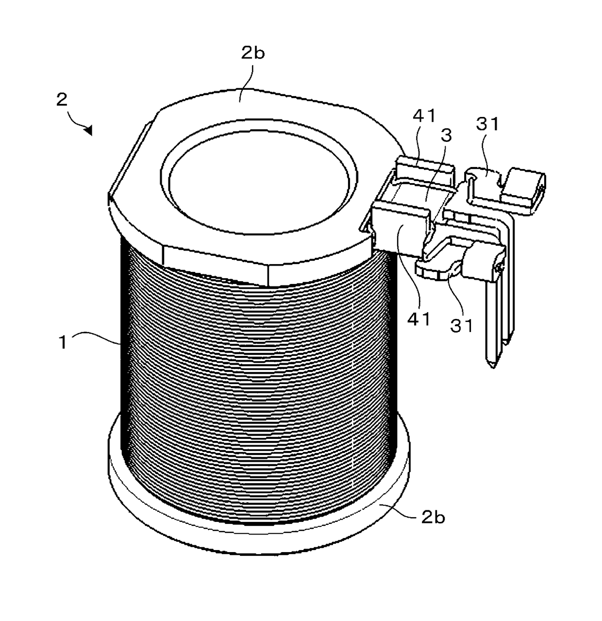
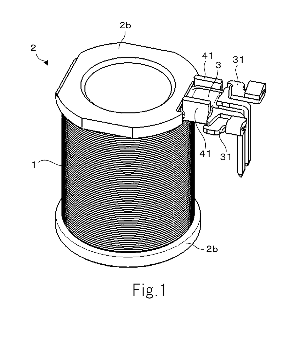
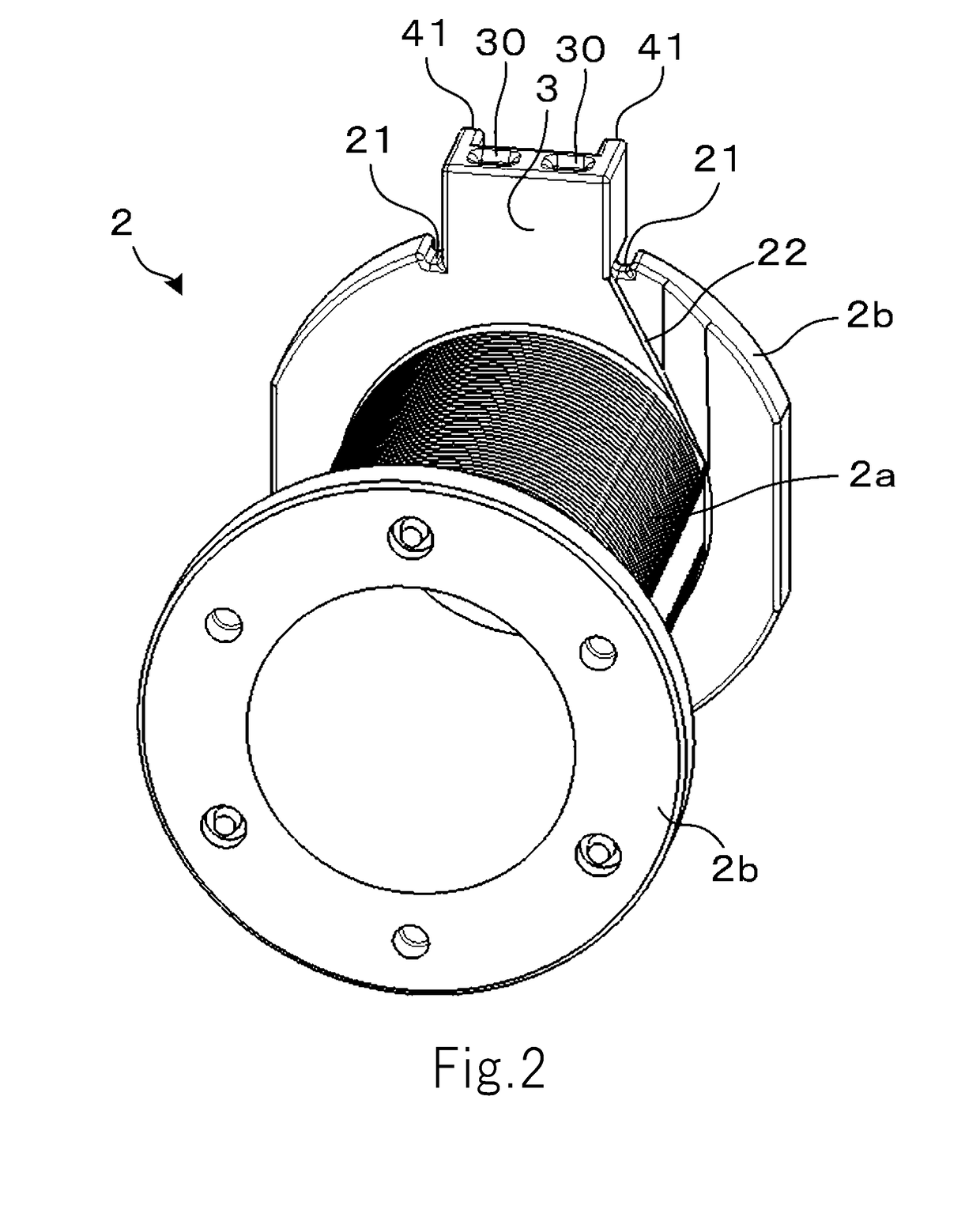
The present disclosure relates to a solenoid of an electromagnetic valve where the number of processes can be reduced and breaking of a conductive wire can be suppressed in a simple structure, and the solenoid of the electromagnetic valve according to the present disclosure comprises a conductive wire; a bobbin having a tubular winding portion where the conductive wire is wound around in a coil shape and a flange portion disposed on both end portions of the winding portion; a terminal portion which is disposed on the flange portion and protrudes in a planar shape in a direction perpendicular to the central axis of the bobbin on a radially outer side than the winding portion relative to the central axis, and in which two terminals are provided on a distal end portion side; and two wall portions which are disposed on both sides of the terminal portion in a width direction, stand upright in a central axis direction and face each other, wherein both end portions of the conductive wire are drawn out from the bobbin to the terminal portion, directed toward a radially outer side from a winding portion side of the two wall portions and electrically connected to the terminals.

Description

CROSS REFERENCE TO RELATED APPLICATIONS[0001]This application claims the benefit of priority to Japanese Patent Application No. 2016-023409 filed on Feb. 10, 2016. The entire contents of this application are hereby incorporated herein by reference.BACKGROUND OF THE INVENTION[0002]1. Field of the Invention[0003]The present disclosure relates to a solenoid of an electromagnetic valve.[0004]2. Description of the Related Art[0005]An electromagnetic valve is used for hydraulic control of an automatic transmission of a vehicle. This electromagnetic valve opens and closes a valve main body connected to a plunger in a hydraulic circuit by driving the plunger made of a piece of iron by the electromagnetic force generated from a solenoid. The solenoid of this electromagnetic valve includes a cylindrical bobbin and an enameled wire wound around the bobbin to form a coil.[0006]Both end portions of the enameled wire wound around the bobbin extend to terminals for connecting with the outside, whi...

Claims


Application Information

Patent Timeline
Patent Type & Authority Patents(United States)
IPC IPC(8): H01F5/00F16K31/06H01F7/20
CPCF16K31/0675H01F7/20H01F5/02H01F5/04H01F7/127H01F2007/062
Inventor ISHII, HIROKIYASUDA, TOMOHIROCHEN, WEIMINGOHIRA, YOSHIHIKOHASHIMOTO, TAKASHIKISHI, MASAYA
Owner NIDEC TOSOK CORP
Learn More