Waterproofing structure for connector

a technology of waterproof structure and connector, which is applied in the direction of coupling device details, electrical discharge lamps, coupling device connections, etc., can solve the problems of increasing the burden of assembling work, the force with which the seal protruding portion is forced, and the housing cannot be fitted to each other in a regular position, so as to reduce the number of components, prevent any defect, and reduce the manufacturing cost of components

Active Publication Date: 2017-09-05
YAZAKI CORP
View PDF11 Cites 3 Cited by
  • Summary
  • Abstract
  • Description
  • Claims
  • Application Information

AI Technical Summary

Benefits of technology

[0010]The present invention is developed in consideration of the aforementioned problems. An object of the invention is to prevent any defect from occurring due to deformation or shaving of a connector when the connector is assembled, while reducing a fitting load with which housings are fitted to each other.
[0012]According to the structure, the annular member is provided at the circumferential edge of the opening end of the first housing, and the second housing is made close to a predetermined position of the first housing so that the circumferential edge of the opening end of the second housing can abut against the inner circumferential surface of the annular member. Thus, the circumferential edges of the opening ends of the two housings can be sealed by the annular member. In addition, according to the structure, the second housing can keep its non-contact state until abutting against the annular member. It is therefore possible to prevent damage such as deformation or shaving during assembling, and it is also possible to reduce the fitting load between the housings.
[0014]According to the configuration, when the annular member is pressed against the second housing, the annular member is elastically deformed so that the widened inner circumferential surface as a whole can be further widened. When the annular member is elastically deformed thus, a restoring force (spring force) derived from the elastic deformation of the annular member acts on the circumferential edge of the opening end of the second housing. Accordingly, the gap between the annular member and the circumferential edge of the opening end of the second housing can be sealed more surely. In addition, when the connector vibrates, the annular member is opened and closed while being elastically deformed. Thus, the vibration can be absorbed. It is therefore possible to suppress propagation of the vibration to each terminal, so that the electrical connection state between the terminals can be kept excellent.
[0016]According to the configuration, the number of components can be reduced. It is therefore possible to reduce the manufacturing cost of the components.
[0017]According to the invention, it is possible to prevent any defect from occurring due to deformation or shaving of a connector when a connector is assembled, and it is possible to reduce a fitting load with which housings are fitted to each other.

Problems solved by technology

Accordingly, due to friction between the seal protrusion portions and the hood portions, there arises a problem that the fitting load with which the housings are fitted to each other becomes large enough to increase the burden of the assembling work.
In this case, when shavings of the seal protrusion portion are put into a gap between the two housings, there is a fear that the housings cannot be fitted to each other in a regular position.
Further, when the seal protrusion portion abutting against the inner hood portion or the outer hood portion is deformed, there is a fear that the force with which the seal protrusion portion can press the inner circumferential surface or the outer circumferential surface of the outer cylinder may be reduced to lower the sealing performance.

Method used


Image

  • Waterproofing structure for connector
  • Waterproofing structure for connector
  • Waterproofing structure for connector

Examples


Embodiment Construction

[0027]An embodiment of a waterproofing structure of a connector to which the invention is applied will be described below with reference to the drawings. Although a waterproof connector to be mounted on a moving body such as a motorcycle is described in the embodiment by way of example, the connector according to the invention can be used to other applications.

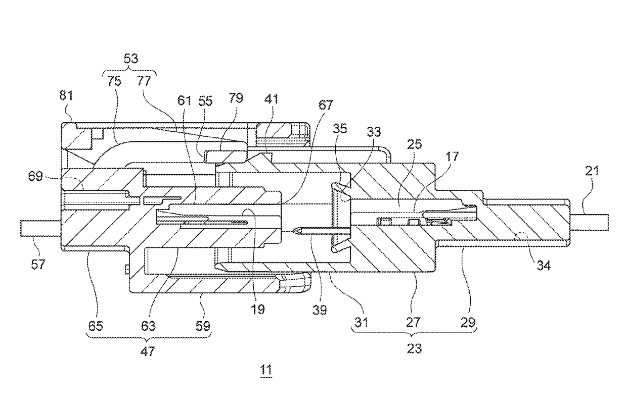
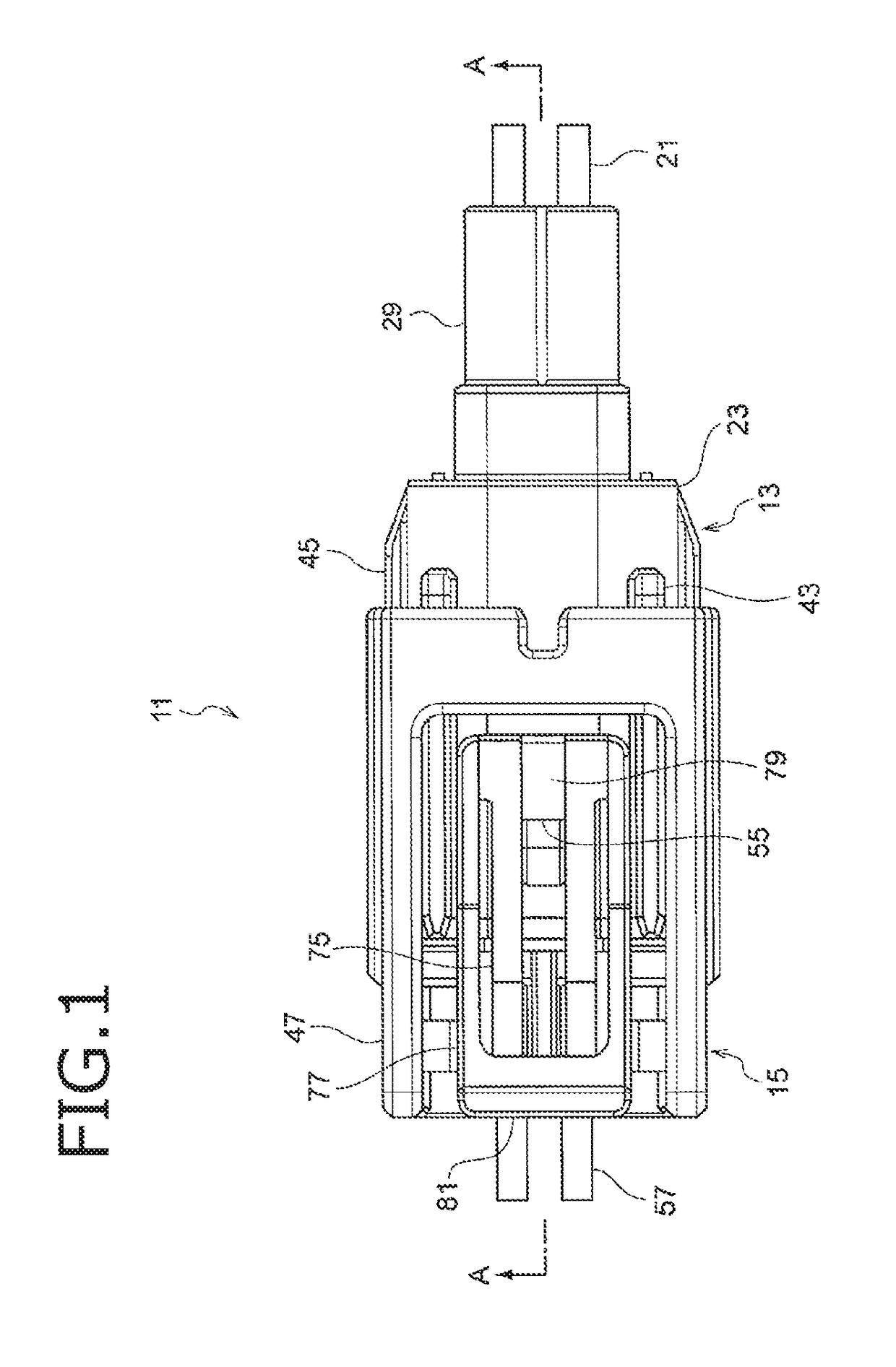
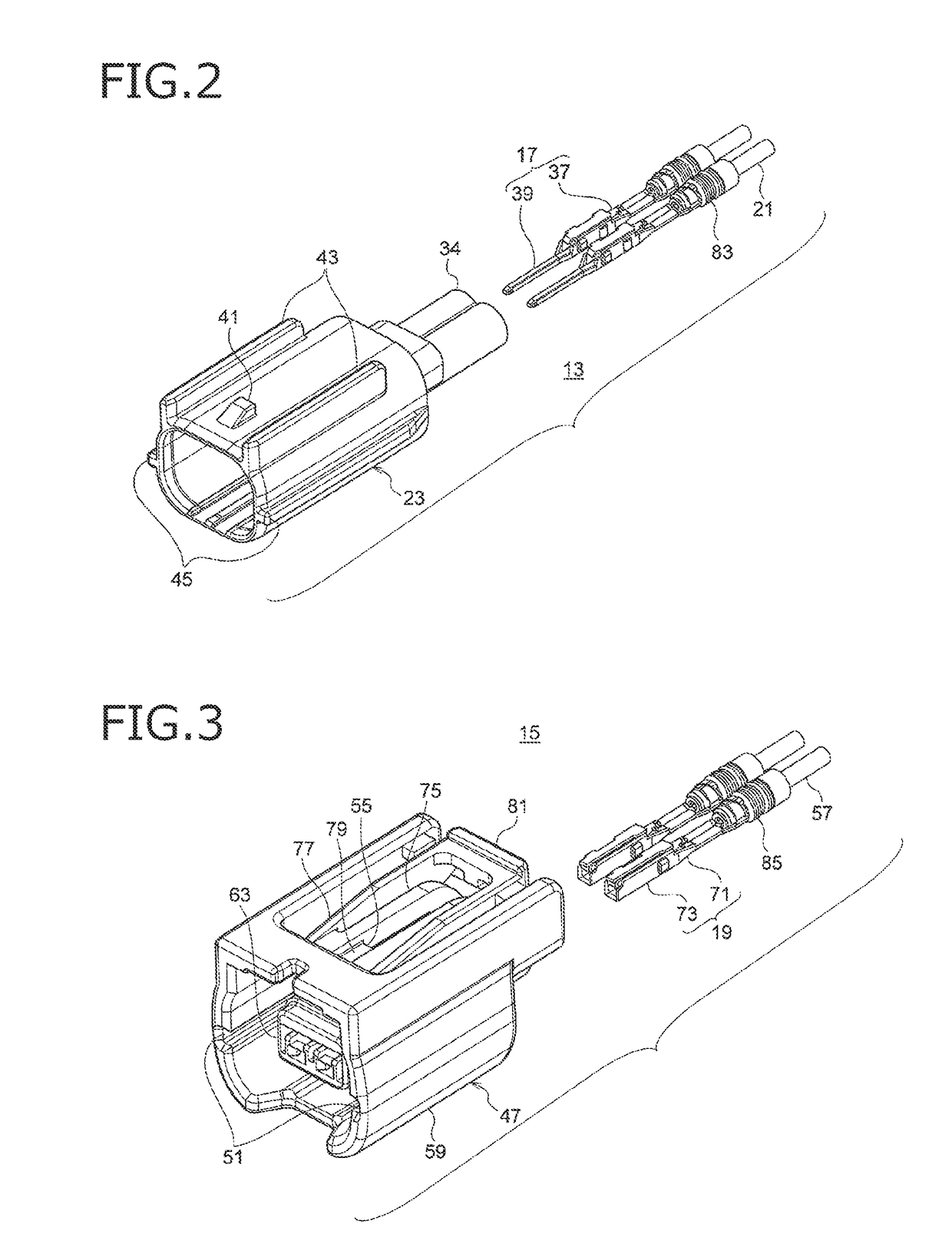
[0028]FIG. 1 is a top view of a waterproof connector according to an embodiment of the invention. FIG. 2 is an exploded perspective view of a male connector constituting the waterproof connector in FIG. 1. FIG. 3 is an exploded perspective view of a female connector constituting the waterproof connector in FIG. 1. FIG. 4, FIG. 5A and FIG. 5B show sectional views taken from the arrow direction A-A in FIG. 1. FIG. 4 shows a state in which the male connector and the female connector are not fitted to each other yet. FIG. 5A and FIG. 5B show a state in which the male connector and the female connector are fitted to each other.

[002...


PUM


Abstract

A waterproofing structure for a connector includes a first housing having a first terminal reception chamber for receiving a terminal and a second housing having a second terminal reception chamber for receiving a terminal. An opening end of the first terminal reception chamber is opposed to an opening end of the second terminal reception chamber, so that a gap with which circumferential edges of the opening ends are opposed to each other is configured to be sealed. An annular member made of resin is provided at the circumferential edge of the opening end of the first terminal reception chamber, the annular member having an inner circumferential surface widened toward the second housing. The circumferential edge of the opening end of the second terminal reception chamber abuts against the inner circumferential surface of the annular member.

Description

CROSS REFERENCE TO RELATED APPLICATIONS[0001]This application is a continuation of PCT application No. PCT / JP2015 / 062744, which was filed on Apr. 27, 2015 based on Japanese Patent Application (No. 2014-093218) filed on Apr. 28, 2014, the contents of which are incorporated herein by reference.BACKGROUND OF THE INVENTION[0002]1. Field of the Invention[0003]The present invention relates to a waterproofing structure for a connector, and particularly relates to a waterproofing structure that seals a gap between connectors without any rubber packing.[0004]2. Description of the Related Art[0005]In the background art, a waterproof connector for connecting different electric wires with each other is mounted on a moving body such as a motorcycle. Such a connector is arranged to include a male housing and a female housing. The male housing receives a male terminal to which an electric wire is connected. The female housing receives a female terminal to which another electric wire is connected. ...

Claims


Application Information

Patent Timeline
Patent Type & Authority Patents(United States)
IPC IPC(8): H01R13/52H01R24/20H01R24/28H01R33/965H01R33/95H01R103/00
CPCH01R13/5216H01R13/5219H01R24/20H01R24/28H01R13/52H01R13/521H01R13/5202H01R33/95H01R33/965H01R2103/00
Inventor HAMADA, KEIJIMIYAKAWA, TOMOYUKI
Owner YAZAKI CORP
Why Eureka
Try Eureka