Photovoltaic mounting system with chemical flashing

a technology of photovoltaic energy and mounting system, which is applied in the direction of heat collector mounting/support, light and heating apparatus, sustainable buildings, etc., can solve the problems of causing another potential leakage point, affecting installation ease, and relatively high price of flashing, so as to reduce or eliminate any mess and improve installation ease

Active Publication Date: 2017-09-05
TESLA INC
View PDF68 Cites 12 Cited by
  • Summary
  • Abstract
  • Description
  • Claims
  • Application Information

AI Technical Summary

Benefits of technology

[0020]In some aspects, the mounting systems are adapted for use with a sealant injection system that provides improved directional release of sealant to seal any roof penetrations while substantially containing the released sealant within the components of the system, thereby reducing or elimination any mess and drastically improving ease of installation. In other aspects, the sealant injection systems described within can be readily positioned within or removed from the associated mounting bracket to allow for ready assembly, replacement or exchange of sealant injection systems as desired. Such configurations allow sealant injection packages to be provided separately as needed for a particular application or as required for the environmental conditions of a geographical area in which the mounting systems are being installed.

Problems solved by technology

Although flashings cover up a lot of space, potentially covering mis-drilled or off-center pilot holes, flashings are relatively expensive because they require more metal than direct mounted solutions.
Each time a nail is removed, another potential leak point is created.
This can be messy for the installer, requires a separate large and bulky tool (e.g., caulk gun), and requires another product SKU to be stocked in the truck's inventory.
Moreover, there is no way to ensure that the installer remembers, or even he does remember, that he actually applies caulk or sealant to the lag holes.

Method used


Image

  • Photovoltaic mounting system with chemical flashing
  • Photovoltaic mounting system with chemical flashing
  • Photovoltaic mounting system with chemical flashing

Examples


Embodiment Construction

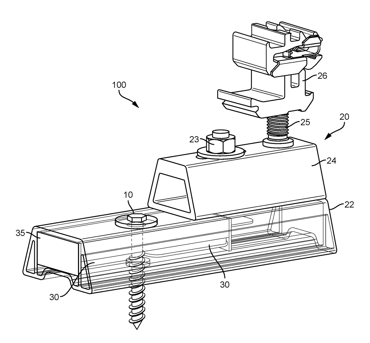
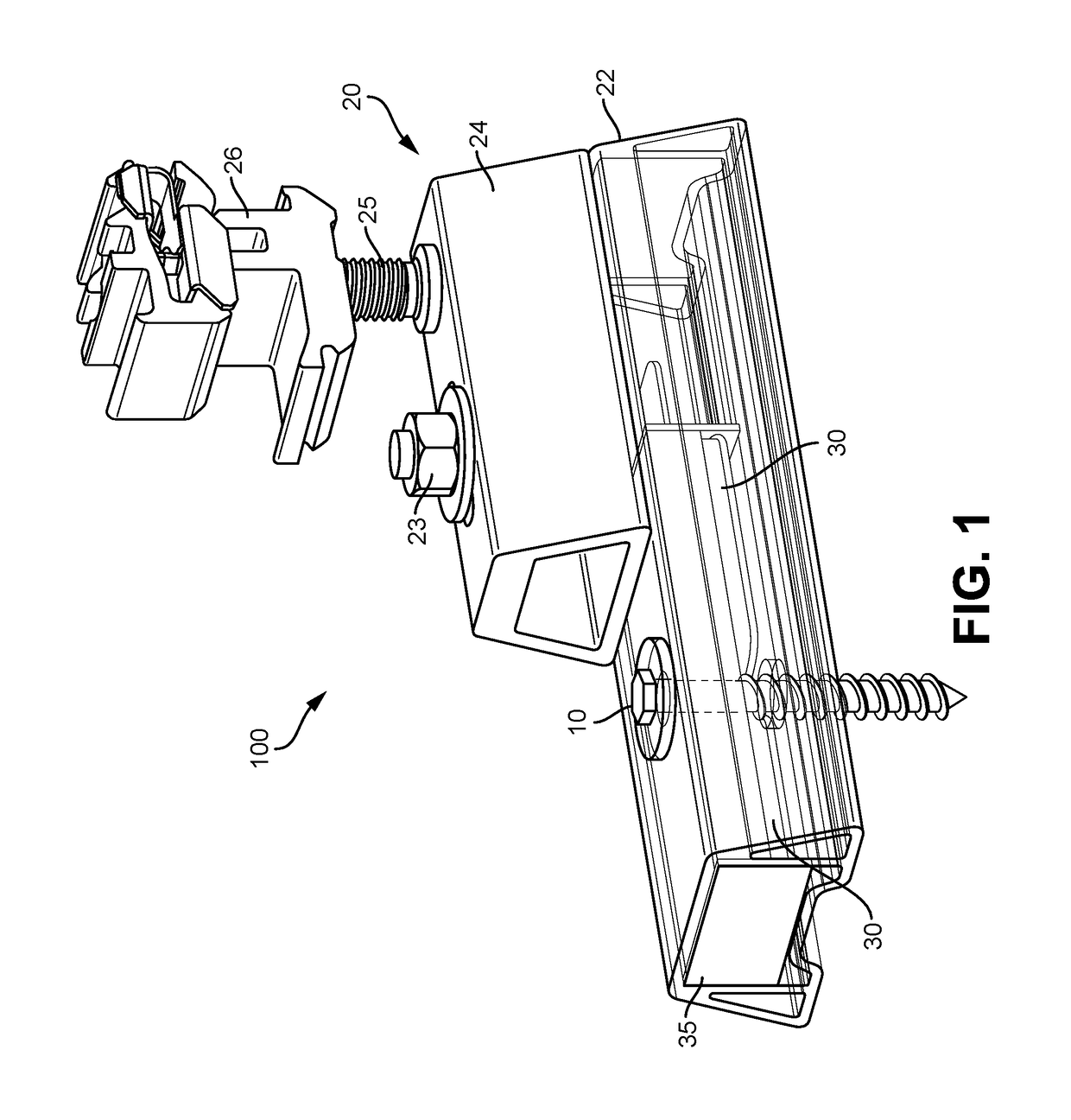
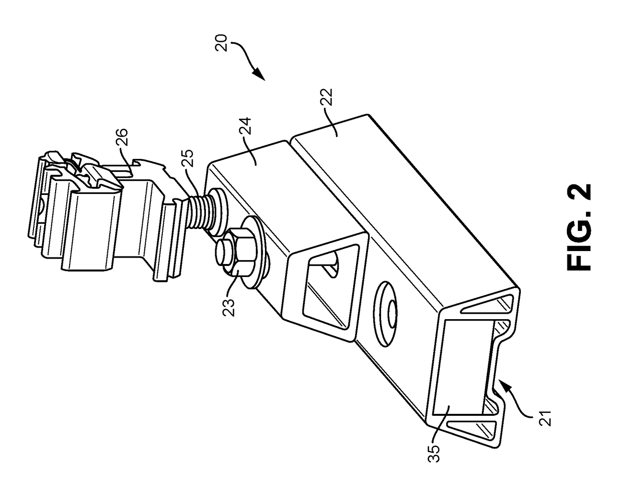
[0044]The present invention seeks to ameliorate some if not all of the shortcomings of the prior art with a photovoltaic mounting system that includes a sealant reservoir and injector mechanism that automatically controls injection of sealant in and around a lag hole as a lag bolt is torqued down to attach the photovoltaic mounting hardware to the roof. In various embodiments, the lag bolt may engage a piston or other structure that comprises a package containing sealant and force sealant to flow between the mounting hardware and the roof surface as the lag bolt is torqued down. In various embodiments, the photovoltaic mounting system may come pre-loaded with the injector system so that the installer can guarantee that sealant is applied to every lag bolt, regardless of whether the installer intentionally does so. In other embodiments, the sealant reservoir is separable from the mounting bracket so that the sealant reservoir can be replaced as needed or assembled according to differ...


PUM


Abstract

Photovoltaic mounting systems having sealant injection system are provided herein. Such sealant injection systems provide improved directional control of sealant flow and improved sealing of roof penetrations during mounting with one or more fasteners. Such systems can include a bracket assembly having a removable sealant injection package. The sealant injection package includes a collapsible sealant injection reservoir and is adapted to provide directionally controlled release of sealant upon collapse. Such a system can further include sealant injection guides that direct flow of sealant during mounting and pads or caps that cover and enclose the injected sealant so as to ensure adequate sealing of any roof penetrations and maintain its integrity over time. Such systems further allow for sealant injection packages to be interchanged or replaced as needed and allow for ready removal or replacement of the bracket after mounting while maintaining the seal of any roof penetrations.

Description

CROSS REFERENCE TO RELATED APPLICATIONS[0001]This claims the benefit of priority of U.S. Provisional Patent Application No. 62 / 120,841 filed on Feb. 25, 2015, the entire contents of which are incorporated herein by reference.FIELD OF THE INVENTION[0002]The invention relates to photovoltaic energy generation mounting systems and more specifically to systems and methods for installing photovoltaic modules on composition shingle roofs.BACKGROUND[0003]Although total market penetration of solar into the relevant base of potential customers remains relatively low in the United States (e.g. less than about one percent), residential and commercial solar installs have enjoyed double digit growth since the mid to late 2000s. Despite this recent success, developments to reduce cost, increase efficiency and improve overall home integration are ongoing and must continue to increase solar's relatively meager market share when compared to fossil fuel-based grid power.[0004]One problem that remains...

Claims


Application Information

Patent Timeline
Patent Type & Authority Patents(United States)
IPC IPC(8): E04D13/18H02S20/23F24J2/52
CPCH02S20/23F24J2/52Y02B10/12F24S25/61F24S2025/021Y02B10/10Y02B10/20Y02E10/47Y02E10/50F24S25/00
Inventor ALMY, CHARLESHUDSON, TYRUS HAWKESWEST, JACK RAYMOND
Owner TESLA INC
Why Eureka
Try Eureka