
Large-size circulating fluidized bed boiler, air distributor and air distributor assembly

a technology of circulating fluidized bed and distributor, which is applied in the direction of lighting and heating apparatus, combustion process, combustion types, etc., can solve the problems of heat absorption adversely affecting the arrangement of heating surfaces, difficult for secondary air to reach the center of the furnace, etc., to reduce vibration and deformation of the panel, increase the heating surface area inside the furnace, and reduce the effect of vibration and deformation

Active Publication Date: 2017-09-26
INST OF ENGINEERING THERMOPHYSICS - CHINESE ACAD OF SCI
View PDF26 Cites 2 Cited by
  • Summary
  • Abstract
  • Description
  • Claims
  • Application Information

AI Technical Summary

Benefits of technology

The present invention addresses the problem of bed-overturn in large-size circulating fluidized bed boilers by providing an air distribution cone with a shape that allows materials and gases in the furnace to freely circulate. Additionally, a T or Y shaped extended heating panel is provided at the top of the air distribution cone, which increases the heating surface area and reduces vibration and deformation of the panel, thereby improving the safety of the boiler. The result is a more uniform flow, improved combustion efficiency, and controlled combustion atmosphere.

Problems solved by technology

With increasing of capacity of a boiler, continuous increasing of cross section of a furnace makes it difficult for a secondary air to reach the center of the furnace.
Meanwhile, with increasing in steam parameters of the boiler, particularly up to supercritical or ultra-supercritical steam parameters, the increasing of a heat emission volume of the furnace is more quickly than the increasing of an evaporation heating surface in the furnace, and the increased imbalance between the heat emission and the heat absorption adversely affects arrangement of the heating surfaces.
Thus, the penetration of the secondary air and the arrangement of the heating surfaces become main technical bottlenecks for the large-sized and the high-parameterized of the circulating fluidized bed boiler.

Method used


Image

  • Large-size circulating fluidized bed boiler, air distributor and air distributor assembly
  • Large-size circulating fluidized bed boiler, air distributor and air distributor assembly
  • Large-size circulating fluidized bed boiler, air distributor and air distributor assembly

Examples


first embodiment

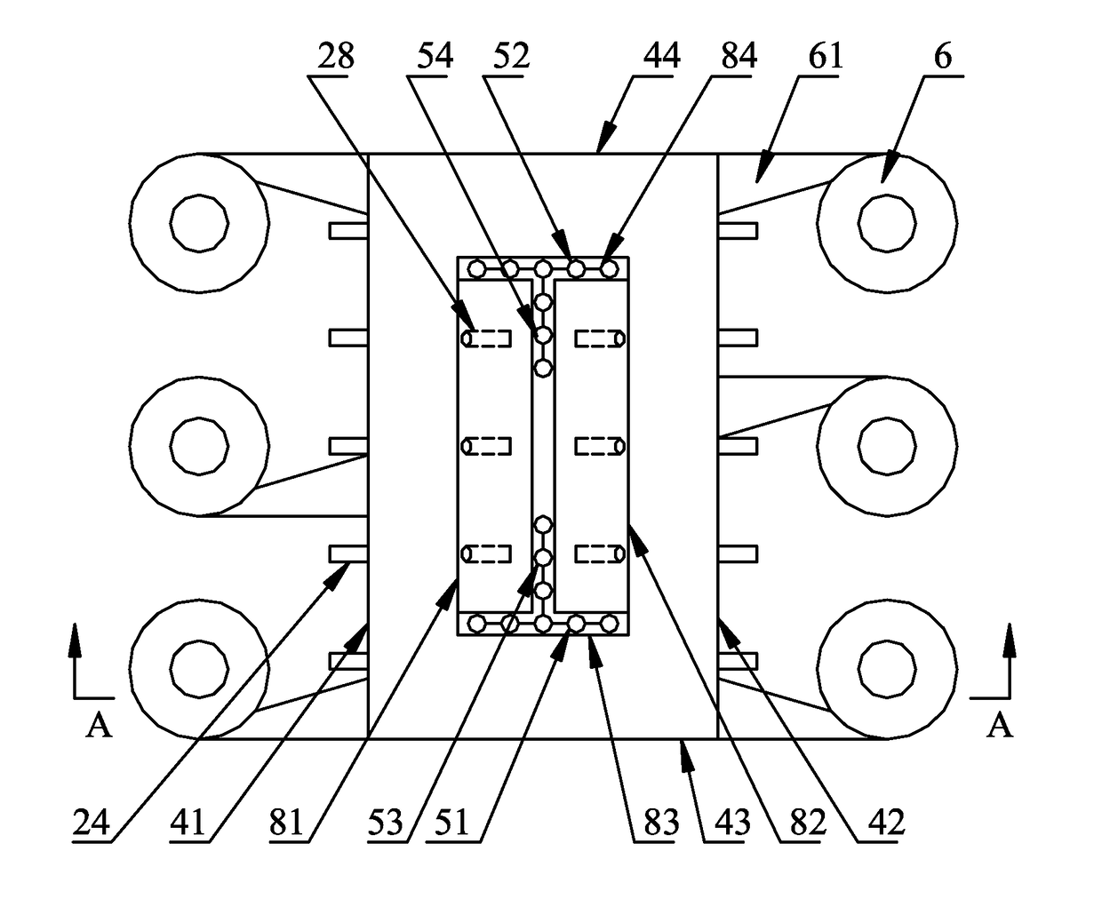
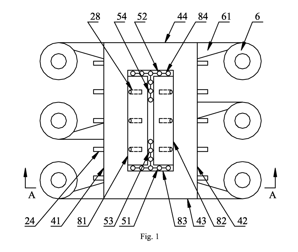
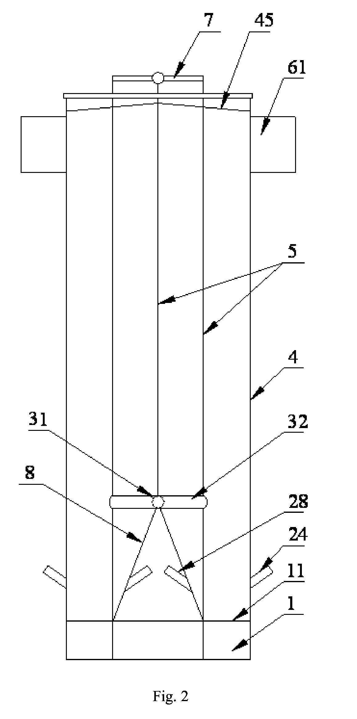
[0077]As shown in FIGS. 1 to 3, a circulating fluidized bed boiler is consisted of a furnace 4 with a air chamber 1 at bottom thereof, cyclone separators 6 with cyclone separator inlet pipes 61, a material returner (not shown in figures) and a backpass (not shown in figures); six cyclone separators 6 are arranged outside of a left side wall 41 and a right side wall 42 of the furnace, an air distribution cone 8, which is rectangular in cross section, is provided on an air distribution plate 11 at the bottom of the furnace 4, so that the air distribution plate 11 of the furnace presents a shape.

[0078]Side walls of the air distribution cone 8 are formed by four membrane water walls coated with refractory materials and surround a hollow space with a bottom opened to atmosphere. As for four side walls of the air distribution cone 8, two side walls 81, 82 opposite to the left and right side wall 41, 42 of the furnace are inclined towards a center of a projection region of a bottom face o...

second embodiment

[0085]As shown in FIG. 8, a circulating fluidized bed boiler is consisted of a furnace 4 with a air chamber 1 at bottom thereof, cyclone separators 6 with cyclone separator inlet pipes 61, a material returner (not shown in figures) and a backpass (not shown in figures); six cyclone separators 6 are arranged outside of a left side wall 41 and a right side wall 42 of the furnace, an air distribution cone 8 is provided on an air distribution plate 11 at the bottom of the furnace 4, so that the air distribution plate 11 of the furnace presents a shape.

[0086]Side walls of the air distribution cone 8 are formed by four membrane water walls coated with refractory materials and surround a hollow space with a bottom opened to atmosphere. As for four side walls of the air distribution cone 8, two side walls 81, 82 opposite to the left and right side wall 41, 42 of the furnace are inclined towards a center of a projection region of a bottom face of the air distribution cone, and form an arris...


PUM


Abstract

The present invention provides a circulating fluidized bed boiler, comprising: furnace side walls; a ceiling; an air distribution plate provided at a bottom of a furnace; and at least one air distribution cone provided on the air distribution plate, wherein each air distribution cone extends upwards from the air distribution plate into an interior of the furnace and has a shape gradually tapered in an extending direction, cone side walls which form the air distribution cone are provided with secondary air ports, the cone side walls are separated from the furnace side walls, and a furnace combustion space is formed and surrounded by the ceiling, the furnace side walls, the air distribution plate, and the cone side walls. The present invention further relates to an air distributor for a circulating fluidized bed boiler, the air distributor being provided on an air distribution plate of the boiler, wherein the air distributor is in a form of an air distribution cone, which extends upwards from the air distribution plate into an interior of a furnace to form a shape gradually tapered in an extending direction, and secondary air ports are formed in air distribution cone side walls forming the air distribution cone. The present invention also relates to an air distributor assembly for a circulating fluidized bed boiler.

Description

FIELD OF THE INVENTION[0001]Embodiments of the present invention generally relate to a circulating fluidized bed boiler, and particularly, to a secondary air distributor of a large-size circulating fluidized bed boiler.DESCRIPTION OF THE RELATED ART[0002]To be large-size and high-parameter is an inevitable trend in the development of a circulating fluidized bed boiler. With increasing of capacity of a boiler, continuous increasing of cross section of a furnace makes it difficult for a secondary air to reach the center of the furnace. Meanwhile, with increasing in steam parameters of the boiler, particularly up to supercritical or ultra-supercritical steam parameters, the increasing of a heat emission volume of the furnace is more quickly than the increasing of an evaporation heating surface in the furnace, and the increased imbalance between the heat emission and the heat absorption adversely affects arrangement of the heating surfaces. Thus, the penetration of the secondary air and...

Claims


Application Information

Patent Timeline
Patent Type & Authority Patents(United States)
IPC IPC(8): F22B31/00F23C10/10F23C10/18F23C10/20
CPCF23C10/10F22B31/003F22B31/0061F22B31/0084F23C10/18F23C10/20
Inventor LV, QINGGANGGAO, MINGSONG, GUOLIANGWANG, XIAOFANGSUN, YUNKAIWANG, DONGYUZHOU, TUO
Owner INST OF ENGINEERING THERMOPHYSICS - CHINESE ACAD OF SCI
Learn More