Film formation apparatus

Inactive Publication Date: 2012-01-12
CANON KK +1
View PDF10 Cites 11 Cited by
  • Summary
  • Abstract
  • Description
  • Claims
  • Application Information

AI Technical Summary

Benefits of technology

[0011]The present invention has been made in view of the above-mentioned problems, and therefore has an object to provide a film formation apparatus capable of reducing vibration and deformation that may be transmitted to an alignment mechanism for performing alignment between a substrate and a film formation mask in the film formation apparatus and thereby suppressing misalignment therebetween.
[0012]A film formation apparatus according to the present invention includes: a film forming chamber provided with a substrate supporting member and a mask supporting member in the film forming chamber; a supporting member provided outside the film forming chamber; and an alignment mechanism provided on the supporting member and provided with at least one of a position adjusting unit for the substrate supporting member and a position adjusting unit for the mask supporting member, and a camera for alignment, wherein: the supporting member includes a supporting plate for placing the alignment mechanism, and a leg portion; the supporting plate is provided so as to be spaced apart from a top board of the film forming chamber via the leg portion; and at least a part of the supporting plate is formed of a damping material capable of converting vibration transmitted to the supporting plate into thermal energy, thereby suppressing the vibration.
[0013]According to the present invention, at least a part of the supporting plate is formed of the damping material capable of converting vibration transmitted to the supporting plate into thermal energy, thereby suppressing the vibration. Hence, the present invention can provide a film formation apparatus capable of reducing vibration and deformation that may be transmitted to the alignment mechanism provided to the film formation apparatus, thereby suppressing misalignment between the substrate and the film formation mask. Therefore, by using the film formation apparatus according to the present invention, it is possible to manufacture an organic EL element and an organic EL apparatus in which an organic compound layer is patterned with less misalignment in a surface direction from a pixel pattern disposed on the substrate and with good dimensional precision.
[0014]Specifically, the level of positional precision that can be increased in the alignment step can be increased, and the positional precision at the stage of the alignment step can be made substantially equal to the positional precision of the pattern formed after the vapor deposition step.

Problems solved by technology

This causes a display defect such as a defect of mixed color.
In other words, slight misalignment between a pixel pattern disposed on the substrate and an aperture pattern of the film formation mask may degrade quality of the organic EL apparatus.
If such distortion is generated in the alignment mechanism, the precision of alignment between the substrate and the film formation mask is lowered to increase the risk of trouble directly leading to the above-mentioned degradation in quality of the organic EL apparatus.
However, misalignment between the substrate and the mask may occur also by vibration transmitted to the alignment mechanism.
An issue of particular concern is that the precision of alignment between the substrate and the mask is affected when vibration generated by peripheral apparatus installed outside the film formation apparatus and the like or vibration accompanying the operation of a transfer robot or the contact or collision operation of respective components provided inside the film formation apparatus is transmitted to the alignment mechanism.
Therefore, the above-mentioned degree of offset caused by the vibration corresponds to a fatal degree.
In the configuration described in Japanese Patent Application Laid-Open No. 2005-248249, the top board of the film formation apparatus and the supporting plate are directly fixed to each other in an integrated manner, and hence there is a fear that the vibration generated inside or outside the film formation apparatus is transmitted to the alignment mechanism via the top board of the film forming chamber and the supporting plate fixed to the top board.
Further, there is another fear that, depending on the position at which the top board of the film formation apparatus and the supporting plate are fixed, slight deformation generated in the film forming chamber as well as the vibration is transmitted to the alignment mechanism via the supporting plate.
As a result, the precision of alignment between the substrate and the film formation mask is lowered by the vibration or the deformation transmitted to the alignment mechanism, and hence the risk of trouble directly leading to the degradation in quality of the organic EL apparatus is increased.

Method used


Image

  • Film formation apparatus
  • Film formation apparatus
  • Film formation apparatus

Examples


example 1

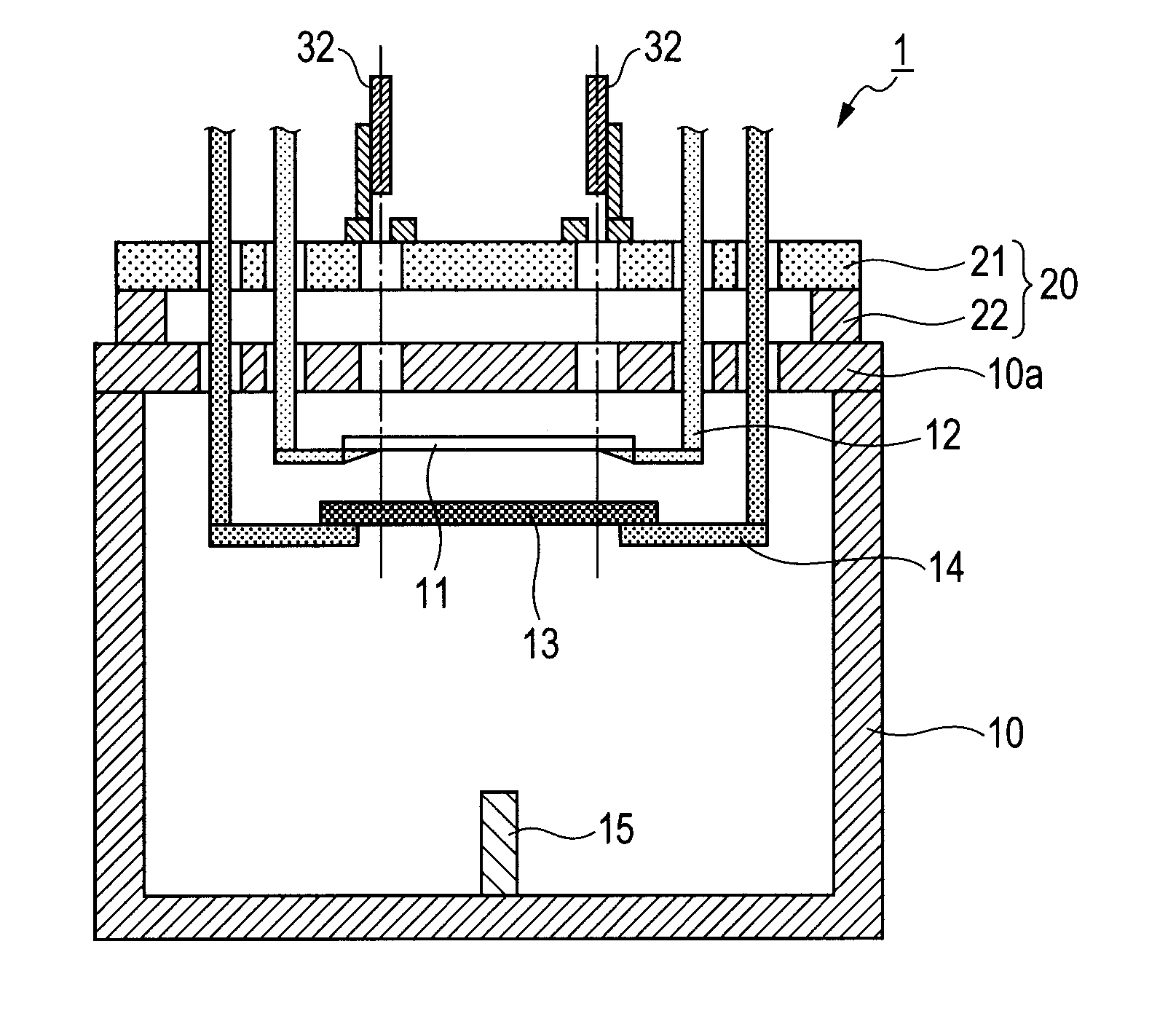
[0053]The film formation apparatus illustrated in FIG.

[0054]1 was used to manufacture an organic EL element on a glass substrate. First, a known light emitting material was placed in the vapor depositing source 15. In the film forming chamber 10, the substrate 11 was located with the surface, on which the film was to be formed, being oriented so as to face downward.

[0055]In this example, the glass substrate made of non-alkali glass with a thickness of 0.5 mm and dimensions of 400 mm×500 mm was used as the substrate 11. Note that, on the substrate, thin-film transistors (TFTs) and electrode wirings were formed in a matrix pattern by a conventional method. Further, the size of each pixel was 30 μm×120 μm. A formation region of the organic EL element was formed to have dimensions of 350 mm×450 mm. Meanwhile, in this example, the mask 13 used was obtained by applying a tension to the mask portion having a thickness of 40 μm and dimensions of 400 mm×500 mm and welding the mask portion to...

example 2

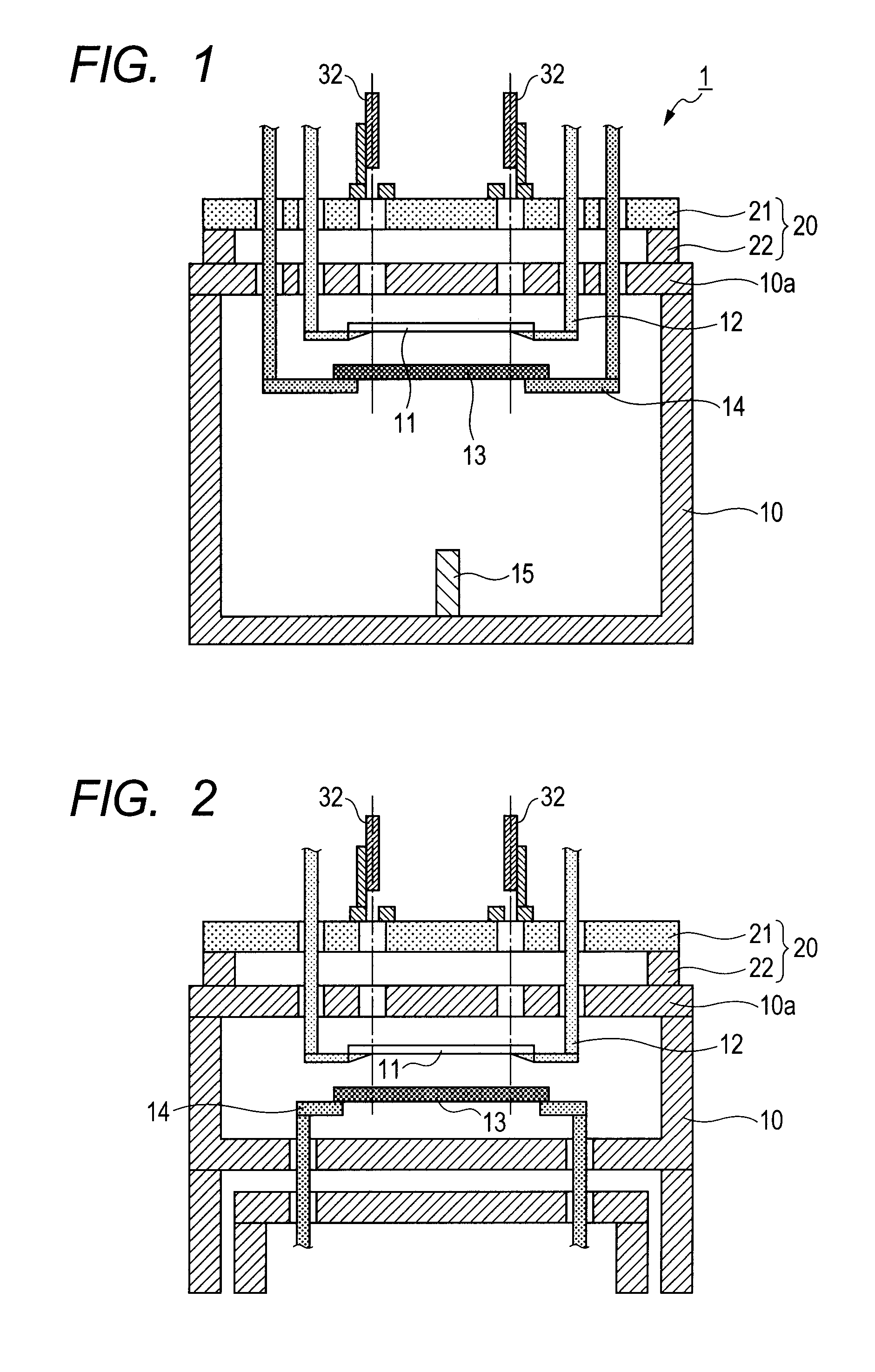
[0064]The film formation apparatus illustrated in FIG. 4 was used to manufacture an organic EL element on a glass substrate.

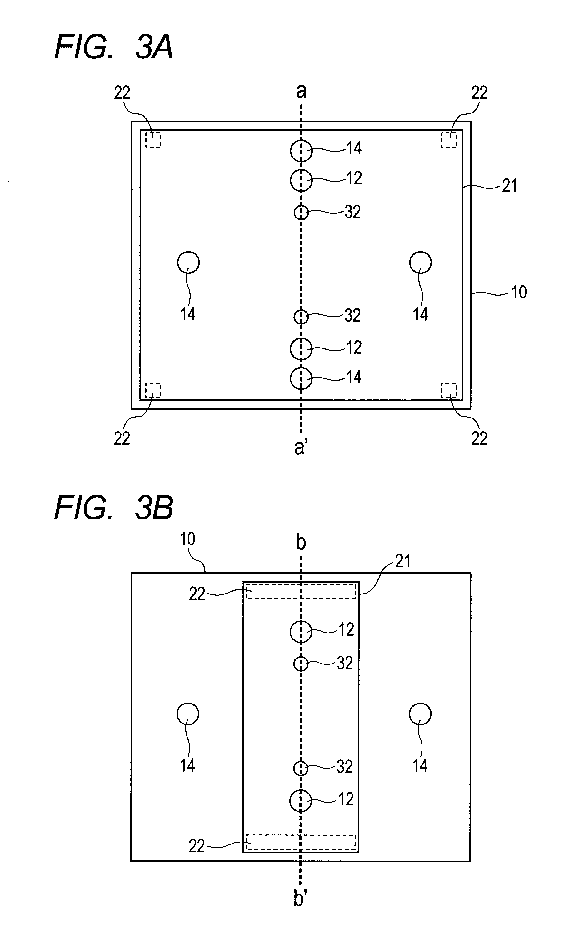
[0065]The supporting member 20 was placed so as to cover and surround the film forming chamber 10 in a U-shaped manner. In this case, the leg portions 22 provided with a vibration insulating member 23 constituted by cast iron and provided at the lower end of each of the leg portions 22 were placed on the floor. Further, on the supporting member 20, the alignment mechanism 30 including the cameras 32, the position adjusting unit of the mask supporting member 12 (not shown), and the position adjusting unit (not shown) for the substrate supporting members was placed.

[0066]Further, the members other than the above-mentioned leg portion 22, the mask, the substrate, and the film formation conditions were the same as those of Example 1.

[0067]Next, as in Example 1, a film was formed of a known light emitting material to have a thickness of 700 Å by using a vacuum vapor...


PUM

PropertyMeasurementUnit
Energyaaaaaaaaaa
Kinetic energyaaaaaaaaaa
aaaaaaaaaa

Abstract

Provided is a film formation apparatus capable of reducing vibration and deformation that may be transmitted to an alignment mechanism and thereby suppressing misalignment between a substrate and a mask in a surface direction. The film formation apparatus includes: a film forming chamber; a supporting member; and an alignment mechanism provided on the supporting member in which: the supporting member includes a supporting plate for placing the alignment mechanism, and a leg portion; the supporting plate is provided so as to be spaced apart from a top board of the film forming chamber via the leg portion; and at least a part of the supporting plate is formed of a damping material capable of converting vibration transmitted to the supporting plate into thermal energy, thereby suppressing the vibration.

Description

BACKGROUND OF THE INVENTION[0001]1. Field of the Invention[0002]The present invention relates to a film formation apparatus.[0003]2. Description of the Related Art[0004]Conventionally, as a method of manufacturing an organic electroluminescence (EL) apparatus, there is widely employed a mask film formation method in which a film formation mask is arranged in close contact with a substrate. An example of the mask film formation method is a mask vapor deposition method. When the mask vapor deposition method is employed, an organic compound layer, which constitutes the organic EL apparatus, can be patterned at a predetermined position with high precision during the formation by a vapor deposition method or a sublimation method.[0005]In recent years, the development of high-resolution organic EL apparatus has led to still finer patterning. For example, in an organic EL display apparatus, the sizes of sub-pixels of red, green, and blue which are repeatedly arranged on a display surface o...

Claims


Application Information

Patent Timeline
IPC IPC(8): B05C11/00
CPCC03C17/002C23C14/54C23C14/12C23C14/042C23C14/04H10K71/00H01J2237/0216
Inventor UKIGAYA, NOBUTAKASODA, TAKEHIKOEIDA, MASATAKAMIYATA, KAZUSHIKAWAGUCHI, YOSHIHIRONODA, SHOUICHI
Owner CANON KK
Why Eureka
Try Eureka