Shell for a hearing device

a hearing device and shell technology, applied in the field of shells for hearing devices, can solve the problems of inability to achieve single-piece and/or single-material shells, and achieve the effects of low production cost, easy removal and cost-effectiveness

Active Publication Date: 2017-09-26
SONOVA AG
View PDF8 Cites 10 Cited by
  • Summary
  • Abstract
  • Description
  • Claims
  • Application Information

AI Technical Summary

Benefits of technology

[0007]In consequence, in the region of the lateral opening or openings, the local rigidity of the shell is reduced, since the local rigidity is only that of the thermoformed hull. On the remainder of the shell, the rigidity is that of the sum of the rigidities of the sub-shell and of the thermoformed hull. In consequence, the local rigidity can be substantially reduced in comparison to single-piece and / or single-material shells e.g. in the regions of the shell subject to pressure from the ear canal during dynamic movement thereof, such as during chewing, talking etc. Due to this reduction in local rigidity, the local flexibility is likewise increased, permitting the shell to flex and deform in response to ear canal movement, reducing discomfort for the wearer. In dimensional terms, the total thickness of the shell can be reduced to 0.1 mm or less, or even down to 20 μm, in the region of the openings in the sub-shell, while the total thickness of the shell can remain at 0.4 mm or greater outside of the region of the openings in the sub-shell, ensuring that the shell as a whole exhibits sufficient rigidity and mechanical stability. With current manufacturing techniques, this is not achievable with a single-piece and / or single-material shell.
[0023]In an embodiment of the method, the thermoformed hull is attached on the exterior of the sub-shell, giving a continuous, smooth outer surface to the shell and allowing the openings in the sub-shell to free up space on the interior of the shell for placement of electronic components. Alternatively, the thermoformed hull is attached on the interior of the sub-shell, leaving the sub-shell exposed and thereby protecting the bulk of the thermoformed hull from damage.

Problems solved by technology

With current manufacturing techniques, this is not achievable with a single-piece and / or single-material shell.

Method used


Image

  • Shell for a hearing device
  • Shell for a hearing device
  • Shell for a hearing device

Examples


first embodiment

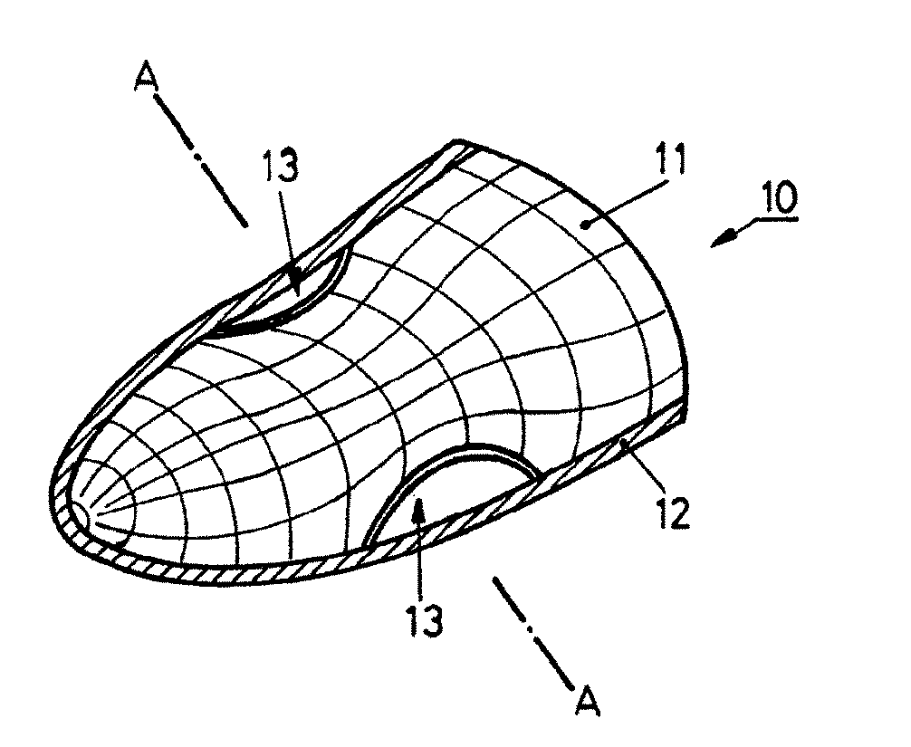
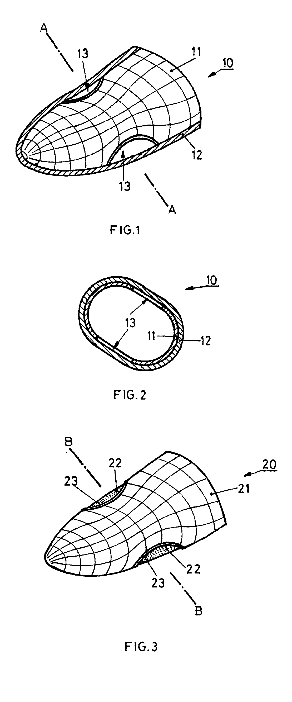
[0042]FIG. 1 illustrates a shell 10 for a hearing device according to the invention, and comprises a closed end (in which ultimately at least one hole will be formed for a sound outlet and / or a wax guard) situated on the left-hand side of FIG. 1, and an open end situated on the right-hand side of FIG. 1. The shell comprises a sub-shell 11 situated inside a thermoformed hull 12. In the view of FIG. 1, the thermoformed hull 12 has been cut away so as to show the structure of the shell 10. Shell 10 may be a shell for an in-the-ear hearing device, particularly an Invisible In the Canal (iiC) hearing device, or may likewise be a shell of an earpiece for a behind-the-ear hearing device.

[0043]Sub-shell 11 is fabricated of a relatively rigid biocompatible material, such as a polymer material or a ceramic-filled polymer material such as UV- or visible light cuarble acrylic resins, and is responsible for the majority of the structural integrity and stiffness of the shell 10. As such, the wall...

second embodiment

[0048]FIG. 3 illustrates a shell 20 for a hearing device according to the invention, which differs from the embodiment of FIGS. 1 and 2 in that the thermoformed hull 22 is situated on the interior of sub-shell 21. This arrangement provides even greater relief from pressure on the ear canal in the areas of openings 23, since the surface of thermoformed hull 22 is below the outer surface of sub-shell 21 by an amount equal to the wall thickness of the sub-shell 21. This, however, comes at the cost of reducing the space available for hearing device components on the interior of the shell 20 in the region of the openings 23.

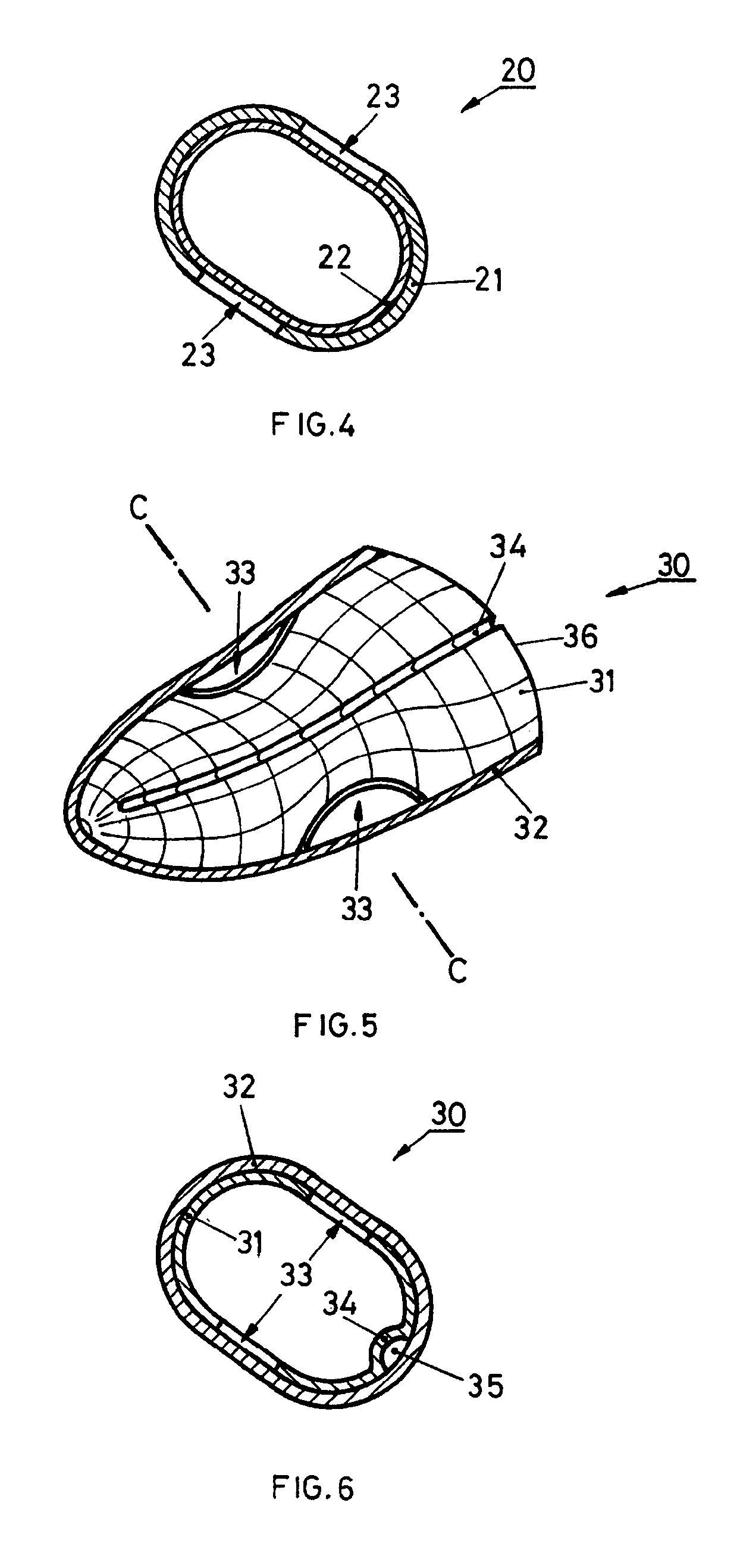
[0049]FIG. 4, in analogy to FIG. 2, illustrates a cross-section of shell 20 along line B-B of FIG. 3, illustrating clearly the arrangement of sub-shell 21 and thermoformed hull 22 on the interior surface thereof. Openings 23 are clearly visible, covered on their interior side by thermoformed hull 22. The above-mentioned comments regarding the joining of sub-shell 11 a...

third embodiment

[0074]the method is represented by the upper track, labelled “A”, on FIG. 11. After the step of thermoforming the polymer film 203 to create the thermoformed polymer film 204, the thermoformed polymer film is attached to the thermoforming mould 200, e.g. by ultrasonic welding. Alternatively, an adhesive may be applied to the polymer film 203 and / or to the thermoforming mould 200 before thermoforming. Subsequently, in step 110, the thermoforming mould 200 has any easily removable sections broken out of it, and is machined as necessary so as to fabricate the sub-shell 206 in situ in the thermoformed hull 205, and the shell is then finished in step 98 as in FIG. 9, and is ready to be assembled into part of a hearing device. This has the advantage that the thermoformed hull 205 is formed in intimate contact with what will become the sub-shell 206, thus improving the matching accuracy of the sub-shell 206 and the thermoformed hull 205. Furthermore, no additional die or sub-shell is requi...


PUM


Abstract

A shell (10) for a hearing device, and a method of producing the same. The shell (10) comprises a sub-shell (11) produced by a generative method, and a thermoformed hull (12) covering the subshell (11). The sub-shell (11) comprises lateral openings (13) covered by the thermoformed hull (12) so as to render the shell (10) more flexible in the region of the openings (13), and thereby to relieve pressure exerted by the shell (10) due to dynamic changes in the shape of the wearer's ear canal during jaw movement.

Description

CROSS-REFERENCE TO RELATED APPLICATIONS[0001]This application is the U.S. National Stage of PCT App. Ser. No. PCT / EP2013 / 050456, filed Jan. 11, 2013.TECHNICAL FIELD OF THE INVENTION[0002]The present invention relates to shells for hearing devices. Hearing devices include hearing aids for the hard of hearing, communication devices, and active hearing protection for loud noises. They are at least partially positioned in the wearer's ear to varying degrees, and may incorporate a behind-the-ear unit situated behind the wearer's pinna and connected either acoustically or electrically with an earpiece.BACKGROUND OF THE INVENTION[0003]Currently, shells for hearing devices, that is to say the outer shell of an In-the-Ear hearing device or the shell of an earpiece of a Behind-The-Ear hearing device, are in general constructed as a hard shell shaped according to an impression or scan taken of the individual's unique ear canal in a static jaw position. Since the shape of the ear canal varies d...

Claims


Application Information

Patent Timeline
Patent Type & Authority Patents(United States)
IPC IPC(8): H04R25/00
CPCH04R25/65H04R25/652H04R25/658H04R2225/021H04R2225/023H04R2225/77H04R2225/0216
Inventor KARAMUK, ERDALSTADLER, MATTHIASWINKLER, THOMASMUELLER, MARKUSPROBST, DANIEL
Owner SONOVA AG
Why Eureka
Try Eureka