Hybrid transfer machine

a transfer machine and hybrid technology, applied in the direction of rotary presses, printing presses, printing presses, etc., can solve the problems of low efficiency of space utilization and high operating costs, and achieve the effect of improving versatility, space utilization and operation efficiency

Active Publication Date: 2017-10-03
KYUNGIL TECH
View PDF5 Cites 0 Cited by
  • Summary
  • Abstract
  • Description
  • Claims
  • Application Information

AI Technical Summary

Benefits of technology

[0010]Accordingly, the present invention has been made keeping in mind the above problems occurring in the prior art, and an object of the present invention is to provide a hybrid transfer machine that can select and use piece mode and roll mode as desired, thereby significantly improving versatility, space utilization and operation efficiency.

Problems solved by technology

Meanwhile, conventionally, since both a roll-type transfer machine and a piece-type transfer machine should be purchased, operating costs are high and space utilization is considerably less efficient because the two machines are arranged in a single space.Reference 1.

Method used


Image

  • Hybrid transfer machine
  • Hybrid transfer machine
  • Hybrid transfer machine

Examples


first embodiment

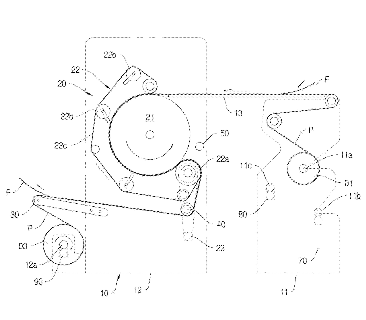
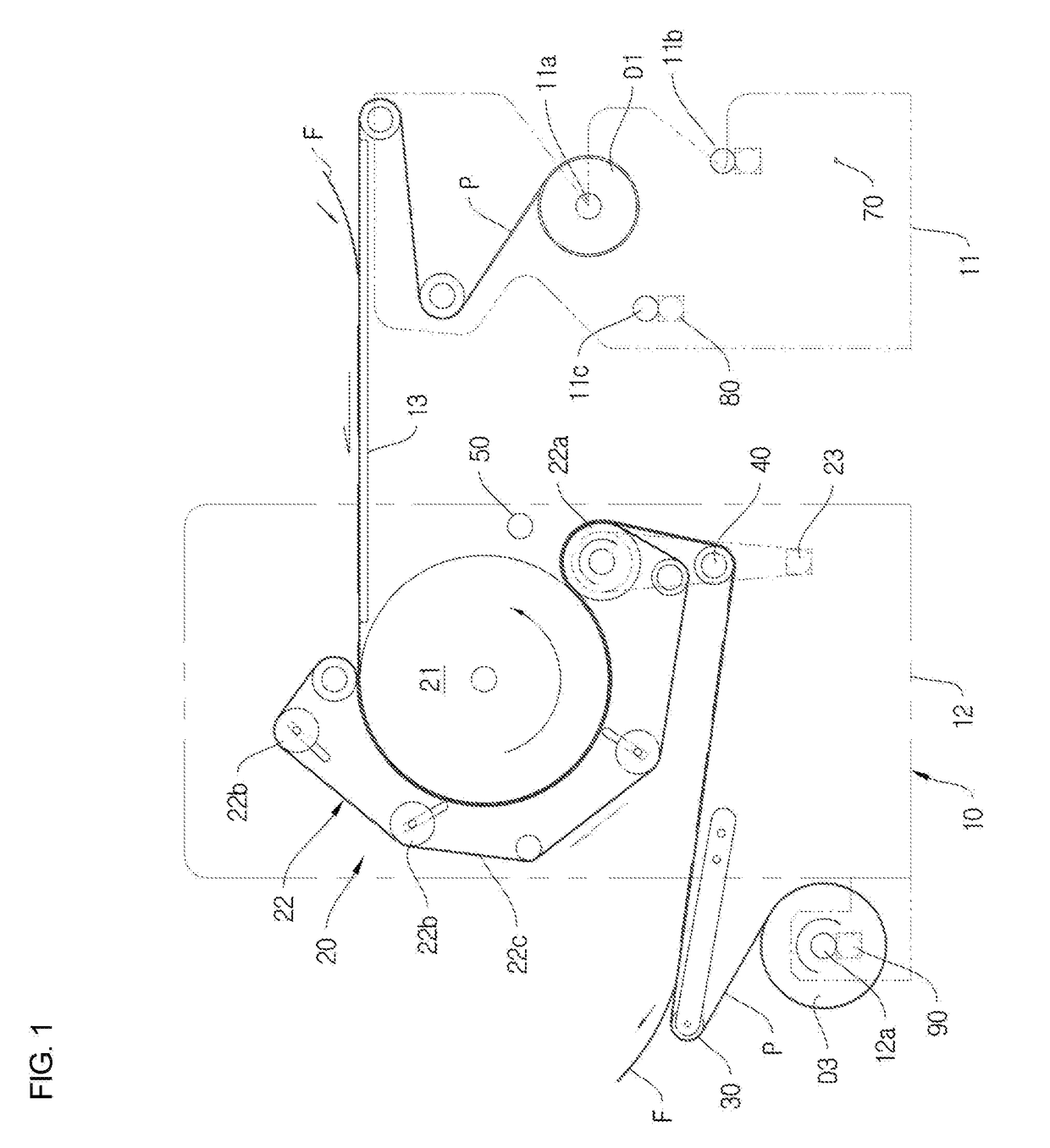
[0030]Referring to FIG. 1, the hybrid transfer machine according to the present invention includes a body 10, a thermal transfer unit 20, a piece-mode roller 30, a main guide roller 40, and a take-up main drum driving means 90.

[0031]Referring to FIG. 1, the body 10 includes a first body 11, a second body 12, and a worktable 13.

[0032]The first body 11 is composed of a pair of plates, and includes a transfer paper supply drum installation portion 11a, a fabric supply drum installation portion 11b, and a take-up transfer paper drum installation portion 11c.

[0033]The second body 12 is also composed of a pair of plates spaced apart from each other, and includes a take-up main drum installation portion 12a.

[0034]The worktable 13 is disposed between and connects the first and second bodies 11 and 12, more accurately between the upper portions of the first and second bodies 11 and 12.

[0035]Referring to FIG. 1, the thermal transfer unit 20 includes a heating drum 21, a close contact mechan...

third embodiment

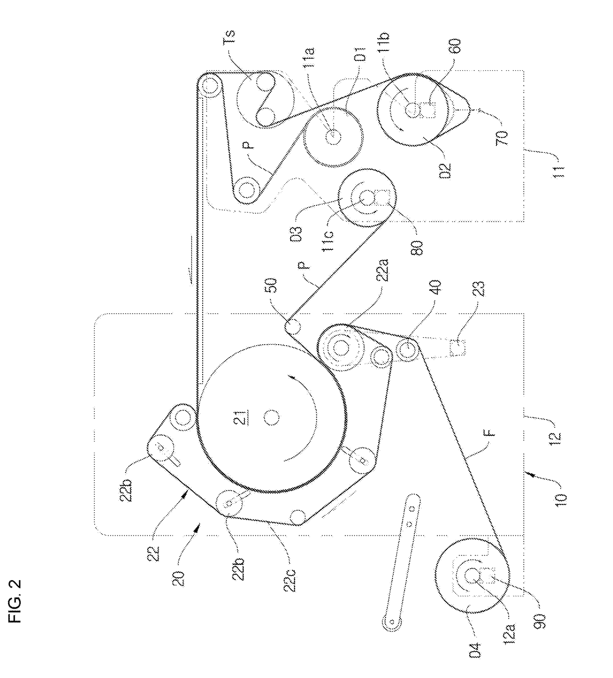
[0080]FIG. 3 is a diagram showing a hybrid transfer machine according to the present invention.

[0081]The construction of the third embodiment of the present invention is substantially the same as the configuration of the above-described second embodiment. They differ from each other in that a tissue supply drum installation portion 12b, a take-up tissue drum installation portion 12c, and a take-up tissue drum driving means 100 are added.

[0082]Referring to FIG. 3, the tissue supply drum installation portion 12b and the take-up tissue drum installation portion 12c are provided in a second body 12.

[0083]A tissue supply drum D5 around which tissue T is wound is rotatably installed on the tissue supply drum installation portion 12b, and a take-up tissue drum D6 configured to wind the tissue T is rotatably installed on the take-up tissue drum installation portion 12c.

[0084]The take-up tissue drum driving means 100 is a servo motor. In the present embodiment, the take-up tissue drum drivi...


PUM


Abstract

A hybrid transfer machine includes a body, a fabric supply drum driving means, a fabric detection sensor, a take-up transfer paper drum driving means, a thermal transfer unit, a piece-mode roller, a take-up main drum driving means, a main guide roller, and a roll-mode roller. The body includes a first body, a second body, and a worktable. The fabric supply drum driving means drives a fabric supply drum. The fabric detection sensor detects fabric, and controls an operation. The take-up transfer paper drum driving means drives the take-up transfer paper drum. The thermal transfer unit heats the fabric and transfer paper. The piece-mode roller rotatably guides the transfer paper. The take-up main drum driving means drives the take-up fabric drum or take-up transfer paper drum. The main guide roller guides the transfer paper or the fabric. The roll-mode roller guides the transfer paper.

Description

CROSS REFERENCE[0001]This application claims foreign priority under Paris Convention to Korean Patent Application No. 10-2015-0163782, filed 23 Nov. 2015, with the Korean Intellectual Property Office.BACKGROUND[0002]The present invention relates generally to hybrid transfer machine, and more particularly to a hybrid transfer machine that can select and use piece mode and roll mode as desired by using a single apparatus.[0003]In general, various patterns are chiefly printed on fabrics, such as those used for handkerchiefs, clothing, etc., using a transfer printing method.[0004]Such a transfer printing method is a printing method in which transfer paper with a specific pattern or photo is laid on printing target fabric, and a heating roller heated to an appropriate temperature is moved in a direction in the state of pressing the transfer paper and the fabric together so that they come into close contact with each other, thereby transferring the pattern or photo on the transfer paper t...

Claims


Application Information

Patent Timeline
Patent Type & Authority Patents(United States)
IPC IPC(8): B41F16/02
CPCB41F16/02D06B11/0076D06P5/003B41M1/00
Inventor JUNG, SOON-TAE
Owner KYUNGIL TECH
Why Eureka
Try Eureka