
Fluid spill containment, location, and real time notification device with cable based sensor

a technology of real-time notification and pipeline, applied in the direction of fluid tightness measurement, pipe couplings, instruments, etc., can solve the problems of catastrophic impact a spill or leak can have on our environment, ecosystems, humans and wildlife, and can persist for years, so as to facilitate construction approval, and reduce the probability and magnitude of pipeline release

Active Publication Date: 2017-10-03
ADLER JEFFREY SCOTT +1
View PDF47 Cites 0 Cited by
  • Summary
  • Abstract
  • Description
  • Claims
  • Application Information

AI Technical Summary

Benefits of technology

[0022]We have designed a fluid spill containment device and system for pipelines carrying energy sources which significantly reduces the probability and magnitude of pipeline releases as a result of its complete integrity and safety management program through containment in a dual wall pipe, instrumentation to sense a release and its accurate location, as well as a real time reporting network to trigger specific repair responses. The device and system are primarily based on the use of cable sensors which in specific combination with the dual wall pipe, which houses an annular bulk-head and spill door option, advantageously serves as a far superior containment and sensory device that would permit a pipeline operator to engage hydrocarbon transport in a safer environment. Whilst the device and system may be more expensive to put in place than a single wall pipeline, its superior autonomous self monitoring / detection, containment and reporting system significantly cuts down on valuable product loss and spill damage to the environment and associated costs, reduces lifetime maintenance costs, facilitates construction approval, and improves goodwill in the community. Advantageously, the device and system is retrofittable into conventional pipe designs presently used in the pipeline industry whereby adaptations are made to these pipes to enable them to serve as the main carrier pipe for the energy source transported.

Problems solved by technology

The transportation of energy sources often occurs over vast distances through rough terrain, difficult environments, important agricultural lands, valuable ecosystems, extreme weather, hydrologically sensitive areas, and potentially unstable regions.
However, an inherent problem with energy source pipelines is the catastrophic impact a spill or leak can have on our environments, ecosystems, humans and wildlife.
Further, as a result of the range of damage that may be caused due to the potentially toxic transported materials, the damage can persist for years.
Whilst a single wall pipe has lower construction and repair costs than a double walled type, single wall pipe failures can release transported toxic materials to the surroundings with devastating results.
Significant releases can occur before detection, resulting in catastrophic damage to the environment, humans and wildlife, as well as loss of goodwill, costly clean up operations and litigation against the pipeline owner / operator.
This design is not suitable for long pipelines due to the limited type of sensors and inability to communicate over long distances.
Since direct measurement at a spill location is not used, the method is subject to false alarms such as an operator changing a valve position, and has insufficient accuracy to detect small but significant leaks.
Also, the method has no provision for spill containment.
To minimize brine requirements, the interstitial space is small, but this makes the example subject to false alarms from carrier pipe expansion and contraction due to carrier transported gas or liquid pressure or temperature changes.
Using a non-corrosive liquid such as glycol risks releasing toxic material to the environment.
The small interstitial space also offers little protection for the carrier pipe from excavation equipment accidental damage.
This method cannot distinguish between carrier pipe and container pipe leaks, and has a great potential for leaking hydraulic fluid into the environment.
The system has no provision for reporting a leak, and it's isolation capability is limited to the distance between valve stations.
The patent refers to previous art which did not use a manifold, and therefore were more costly.
Scaling Berg's approach (or any of his referenced art approaches) to typical pipelines is cumbersome at best, and Berg's approach provides poor leak isolation information.
Smith's approach disadvantageously uses an old pipe for containment which is likely to fail when pressurized by a leak from the new inner pipe, and it makes no claims for leak isolation and reporting capability.
Matalena's approach is cumbersome to implement due to the triple wall construction, the large volumes of glycol needed, and the leak prone plumbing needed to cool and distribute the glycol.
There is no method defined for preventing the glycol from leaking into the permafrost.
The oil / glycol separator is unlikely to be able to accommodate large flow rate oil leaks.
And there is no method defined for collecting and reporting sensor data.
Considering that pipelines transport petroleum products at high pressure, a leak of even moderate rate would quickly fill up any practical sized collection vessel, causing the jacket to burst.
Also, there is no teaching of leak location reporting.
While the method would seem to work for small leaks, even moderate leaks would require a large pump at each collection casing, which would be a considerable expense, considering it would seldom be required.
Reducing that expense by spacing the pumps far apart results in a long section of pipe which would have to be possibly dug up and cleaned before being returned to service.
Leak location reporting is inaccurate, being limited to the distance between collection casings.
Disadvantageously, the spiral cables require calibration for accurate leak location by installing acoustic generators at measured distances on the pipes during construction and recording the results.
And the spiral cables limit the length of pipe which can be sensed, resulting in more monitor stations being required.
While as few as one linear cable is taught, multiple cables are taught for increased performance, which is a complex approach.
Leak location accuracy is limited to the distance between sensor pads, and since the sensor pad readings are affected by heat transfer with the surrounding sea water, small to moderate leaks are unlikely to be detected.
Leak location accuracy is limited to the distance between field joints, and small leaks are unlikely to be detected, since they do not adequately affect pipeline temperature.

Method used


Image

  • Fluid spill containment, location, and real time notification device with cable based sensor
  • Fluid spill containment, location, and real time notification device with cable based sensor
  • Fluid spill containment, location, and real time notification device with cable based sensor

Examples


Embodiment Construction

[0044]As used herein, the term “fluid” is intended to mean gas, natural gas; liquid, including chemicals (synthetic, organic and inorganic including natural food liquids), crude oil, petroleum, oil sand oil, and water, liquefied gas, such as propane, butane, liquefied natural gas, and the like.

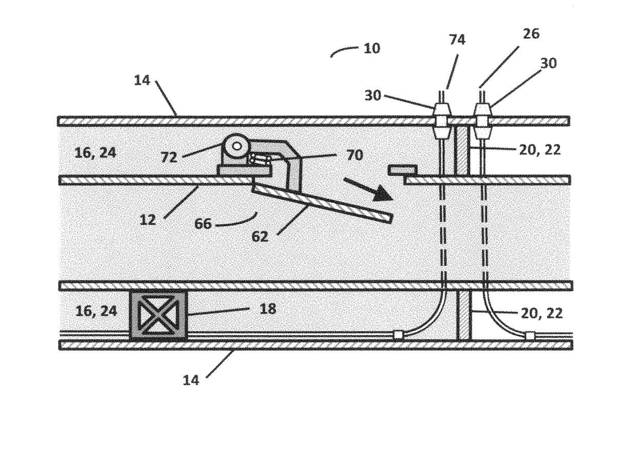
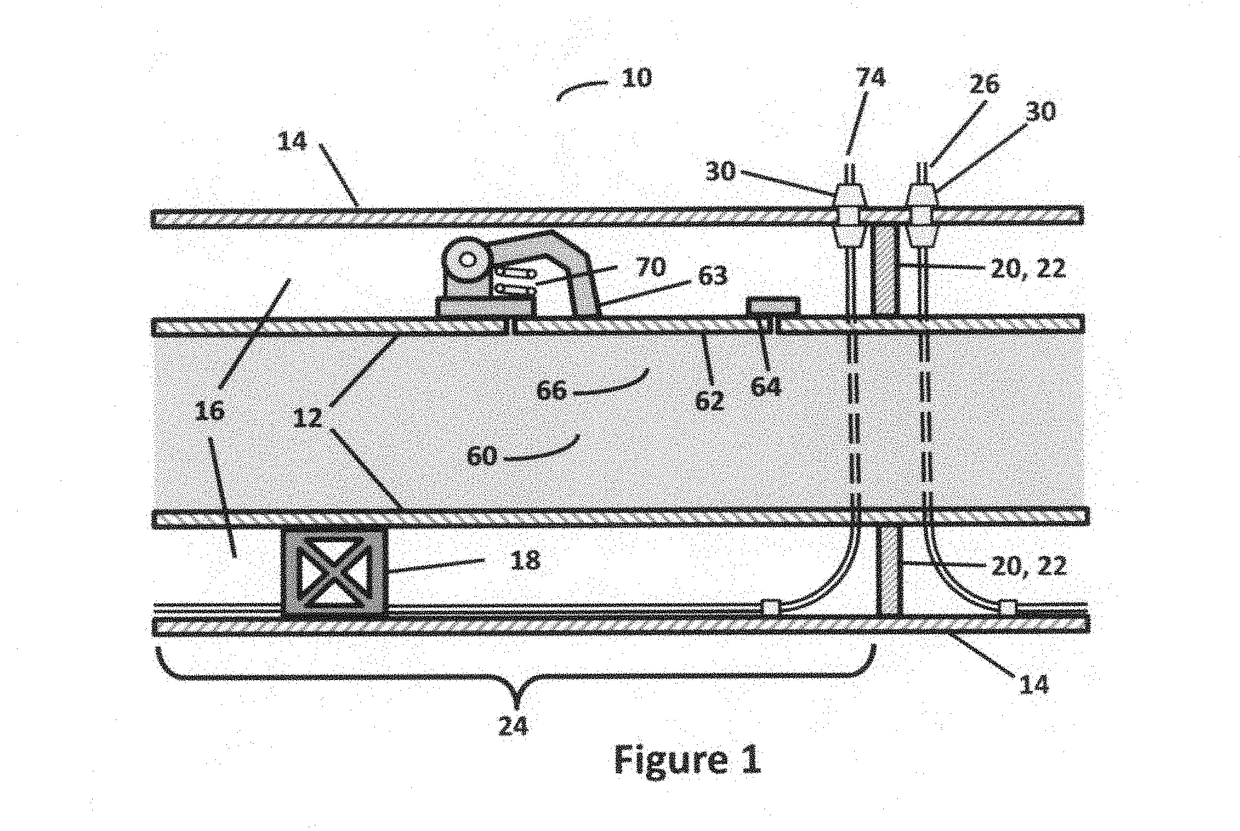
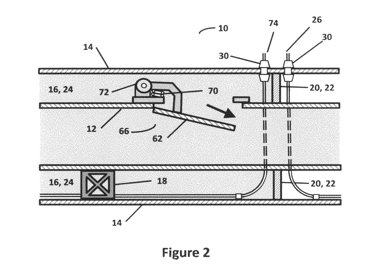
[0045]Referring to FIGS. 1 and 2, there is illustrated generally at 10 a fluid spill containment device. Broadly speaking, the device 10 comprises a double wall pipeline which includes an inner carrier conduit (pipe) 12 and an outer containment conduit (pipe) 14 which encases the carrier pipe 12, and which defines an interstitial space 16 around the carrier pipe 12. The carrier pipe 12 carries the fluid therealong. The interstitial space 16 receives fluid that spills from the carrier pipe 12 in the event that the carrier pipe 12 breaks or is structurally compromised. A plurality of spacers 18 are disposed substantially along the entire length of the pipeline and maintain separation between pip...


PUM


Abstract

Described herein is an autonomous fluid spill containment device for a pipeline which has a carrier conduit for transporting a fluid and a containment conduit located around the carrier conduit to define an interstitial space for receiving fluid spilled from the carrier conduit. The device includes a spilled fluid barrier for stopping spilled fluid flow. The fluid barrier is located in the interstitial space and extending between the carrier conduit and the containment conduit. A cable sensor is associated with the containment conduit for detecting spilled fluid flowing in the containment conduit.

Description

TECHNICAL FIELD[0001]The present relates to fluid transportation using pipelines, and more particularly to a fluid spill containment, accurate location, and real time notification device and system for use with pipelines.BACKGROUND[0002]Pipeline transportation of energy sources has never been so important to the energy infrastructure and consumption of developing nations. Our economies and base of manufacturing rely heavily on the safe and timely provision of energy that may be transported through pipelines in different forms. This quest for energy sources has made the necessity of pipelines an inherent component in our society as a result of their ability to economically transport large volumes of liquids and gases. From crude oil to liquid natural gas, to tar sand oil: the reliable delivery of these valuable commodities for processing or immediate use has never been so important to powering our homes, businesses, towns, cities and nations. The transportation of energy sources ofte...

Claims


Application Information

Patent Timeline
Patent Type & Authority Patents(United States)
IPC IPC(8): G01M3/18G01M3/16G01M3/28F16L9/18
CPCF16L9/18G01M3/165G01M3/18G01M3/283F16L2201/30G01M3/16G01M3/28
Inventor ADLER, JEFFREY SCOTTBAIRD, HAROLD RUSSELL
Owner ADLER JEFFREY SCOTT
Learn More