Methods and apparatus for coded time-of-flight camera

a time-of-flight camera and coded technology, applied in the field of time-of-flight cameras, can solve the problems of multipath interference, mixing pixel problems, and conventional tof cameras that do not accurately measure scene depth in the case of mixed pixels, and achieve the effect of accurately measuring scene depth

Active Publication Date: 2017-10-03
MASSACHUSETTS INST OF TECH
View PDF2 Cites 5 Cited by
  • Summary
  • Abstract
  • Description
  • Claims
  • Application Information

AI Technical Summary

Benefits of technology

[0004]In illustrative embodiments of this invention, the mixed pixel problem is solved: a ToF camera accurately measures scene depth, even at mixed pixels, while using only one fundamental modulation frequency.
[0006]In illustrative embodiments, this invention has numerous practical applications, including: (a) accurately measuring depth, even in the presence of multipath interference; (b) accurately measuring both foreground and background depths, in a scene in which a nearly transparent object in the foreground blocks a direct view of the background; (c) accurately measuring depth of the background of a scene, even when a direct view of the background is blocked by a diffuser; and (d) capturing light sweep images.
[0011]First, the m-sequence tends to minimize the condition number of the smearing matrix (discussed below), thereby making the smearing matrix easily invertible. The condition number of the smearing matrix is the ratio of the largest to the smallest eigenvalues of the smearing matrix and is indicative of the sensitivity of the solution to noise.
[0019]Thus, in illustrative embodiments of this invention, a broadband code has the following advantages: it reduces the condition number of the smearing matrix of the ToF camera, and makes the smearing matrix well-conditioned and easily invertible.

Problems solved by technology

However, conventional ToF cameras do not accurately measure scene depth in the case of mixed pixels—that is, pixels that receive light from multiple depths of the scene.
The mixed pixel problem is sometimes called multipath interference.

Method used


Image

  • Methods and apparatus for coded time-of-flight camera
  • Methods and apparatus for coded time-of-flight camera
  • Methods and apparatus for coded time-of-flight camera

Examples


Embodiment Construction

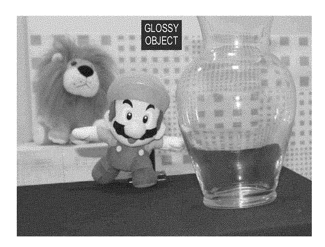
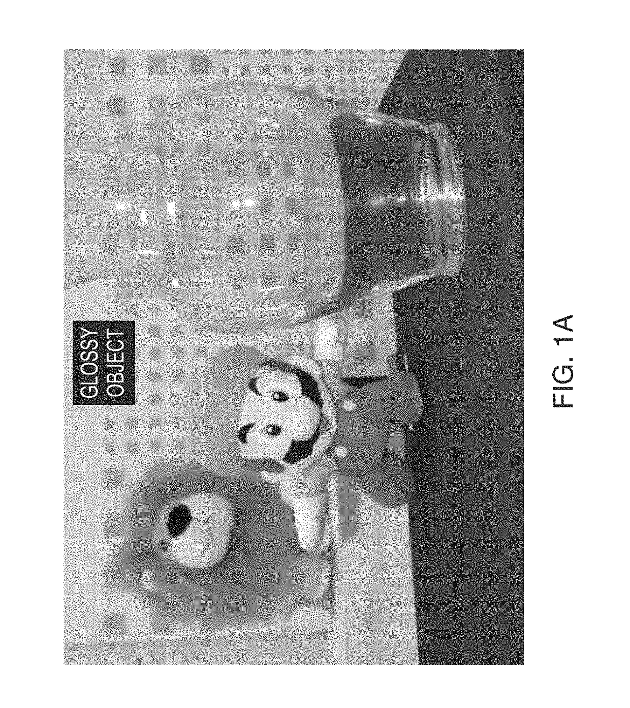
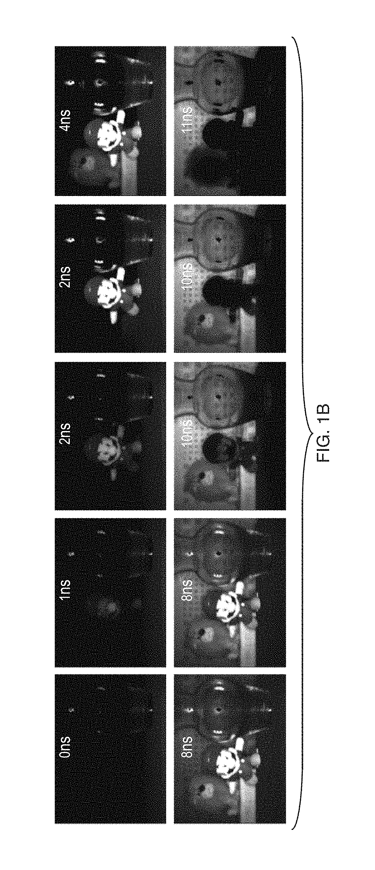
[0067]Conventional time-of-flight (“ToF”) systems achieve depth ranging by amplitude modulation of a continuous wave. These conventional ToF systems assume a single optical path length (range or depth) value per pixel the scene, although the scene may actually consist of multiple depths, e.g., a transparency in front of a wall. If there are multiple depths in a scene, then there are multiple path lengths (from the light source, to the scene, and back to the ToF camera), and a single pixel may receive light reflected from multiple depths in the scene. This scenario (which occurs when multiple light-paths hit the ToF sensor at the same pixel) is commonly known as a “mixed pixel” or “multipath interference”. A conventional ToF camera cannot accurately determine the depth of a mixed pixel; instead, a conventional ToF camera measures a range that is a non-linear mixture of the incoming light paths

[0068]In illustrative implementations, this invention solves or mitigates the mixed pixel pr...


PUM


Abstract

In illustrative implementations, a time-of-flight camera robustly measures scene depths, despite multipath interference. The camera emits amplitude modulated light. An FPGA sends at least two electrical signals, the first being to control modulation of radiant power of a light source and the second being a reference signal to control modulation of pixel gain in a light sensor. These signals are identical, except for time delays. These signals comprise binary codes that are m-sequences or other broadband codes. The correlation waveform is not sinusoidal. During measurements, only one fundamental modulation frequency is used. One or more computer processors solve a linear system by deconvolution, in order to recover an environmental function. Sparse deconvolution is used if the scene has only a few objects at a finite depth. Another algorithm, such as Wiener deconvolution, is used is the scene has global illumination or a scattering media.

Description

RELATED APPLICATIONS[0001]This application is a non-provisional of, and claims the benefit of the filing date of, U.S. Provisional Patent Application No. 61 / 895,132, filed Oct. 24, 2013, the entire disclosure of which is herein incorporated by reference.FIELD OF THE TECHNOLOGY[0002]The present invention relates generally to time-of-flight cameras.BACKGROUND[0003]In a conventional time-of-flight (ToF) camera, scene depth is measured based on the difference between the phase of light emitted by the camera and the phase of light reflected from the scene. However, conventional ToF cameras do not accurately measure scene depth in the case of mixed pixels—that is, pixels that receive light from multiple depths of the scene. The mixed pixel problem is sometimes called multipath interference.SUMMARY OF INVENTION[0004]In illustrative embodiments of this invention, the mixed pixel problem is solved: a ToF camera accurately measures scene depth, even at mixed pixels, while using only one funda...

Claims


Application Information

Patent Timeline
Patent Type & Authority Patents(United States)
IPC IPC(8): G01S17/89G01S17/32G01S7/491G01S7/4915G01S17/894
CPCG01S17/89G01S7/4915G01S17/32G01S17/894
Inventor KADAMBI, ACHUTAWHYTE, REFAELBHANDARI, AYUSHSTREETER, LEEBARSI, CHRISTOPHERDORRINGTON, ADRIANRASKAR, RAMESH
Owner MASSACHUSETTS INST OF TECH
Why Eureka
Try Eureka