Flexible antenna and method of manufacture

Active Publication Date: 2017-10-03
UNIV OF SOUTH FLORIDA +2
View PDF8 Cites 9 Cited by
  • Summary
  • Abstract
  • Description
  • Claims
  • Application Information

AI Technical Summary

Benefits of technology

[0009]In the present invention, the flexibility of a multilayer antenna structure is improved by using overlapping metal plates (fish-scale) which dramatically reduces the rigidi

Problems solved by technology

However, the antennas resulting from these fabrication techniques are narrowband and do not meet the wideband requirements of many modern applications.
The overall stiffness of the antenna increases with the cube of the substrate thickness and stress increases linearly with the thickness of the substrate, the

Method used


Image

  • Flexible antenna and method of manufacture
  • Flexible antenna and method of manufacture
  • Flexible antenna and method of manufacture

Examples


Embodiment Construction

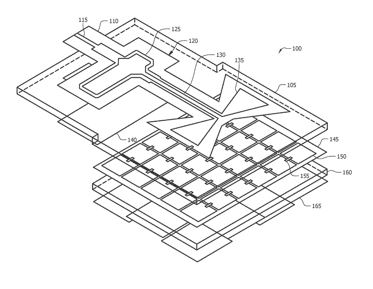
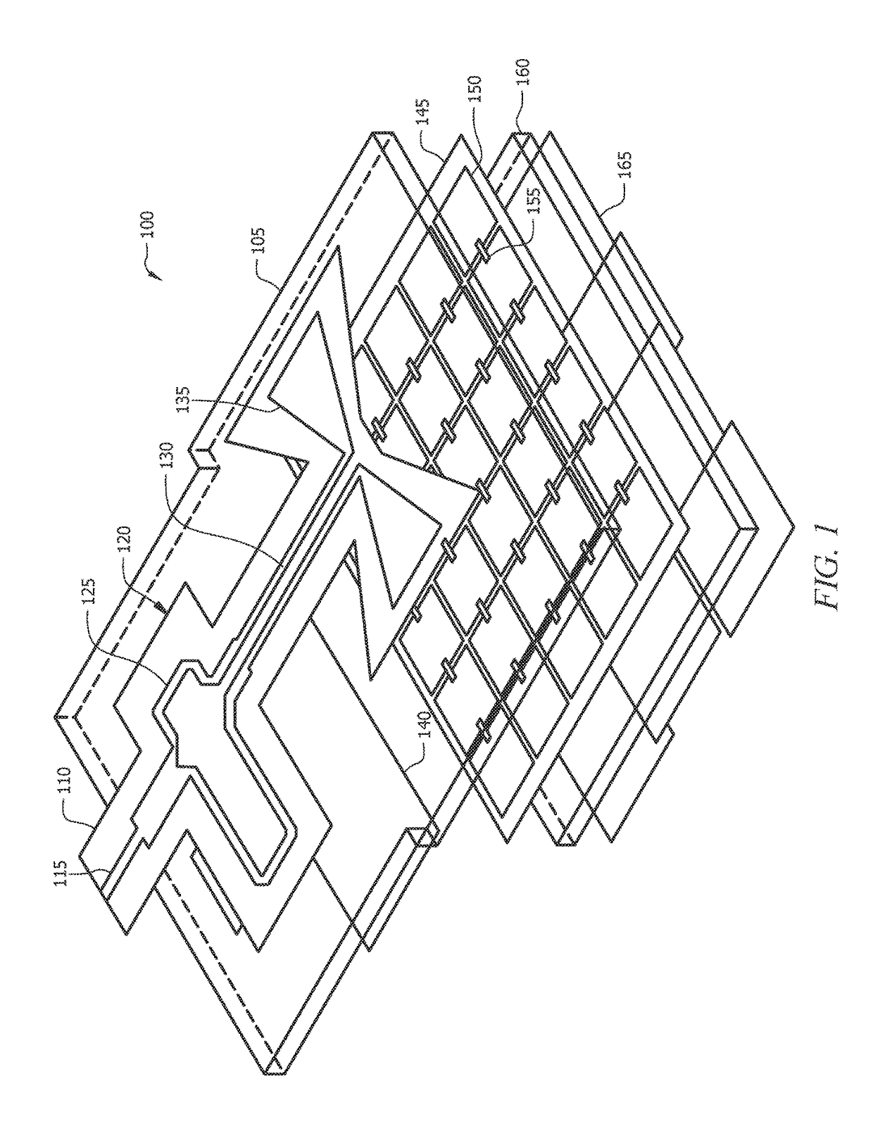
[0035]In various embodiments, the present invention provides a flexible, low profile, dipole antenna backed with a frequency selective surface (FSS) and overlapping metallic plates on the ground plane to improve the flexibility of the structure.

[0036]With reference to FIG. 1, the flexible antenna 100 of the present invention includes a first substrate 110 comprising a planar dipole antenna 120 fabricated on a first surface of the first substrate 110 and a balun ground plane 140 fabricated on a second surface of the first substrate 105. In one embodiment, the first substrate 110 is a liquid crystal polymer (LCP) copper-clad substrate. In one embodiment, the planar dipole antenna 120 may include a microstrip line 115, a microstrip-to-coplanar strip balun 125, a pair of coplanar strips 130 and a radiating dipole element 135. In this embodiment, the balun ground plane 140 is positioned below the microstrip line and the balun 125.

[0037]The flexible antenna 100 further includes a first fl...


PUM


Abstract

A flexible microwave antenna having a “fish-scale” ground plane is provided. The approach represents a significant advance in the combined thickness and flexibility that can be achieved, especially when using relatively thick substrates which are important for optimum antenna performance. An increase in gain was observed when bent in a positive radius of curvature and further reduction of back radiation.

Description

CROSS-REFERENCE TO RELATED APPLICATIONS[0001]This application claims priority to U.S. Non-Provisional patent application Ser. No. 14 / 691,201 filed on Apr. 20, 2015, issued as U.S. Pat. No. 9,531,077 on Dec. 27, 2016, which claims priority to U.S. Provisional Patent Application No. 61 / 981,539 filed on Apr. 18, 2014, both of which are hereby incorporated by reference into this disclosure.BACKGROUND OF THE INVENTION[0002]In recent years, interest in the development of low profile, flexible, tunable, microwave antennas for portable applications, such as wearable electronics, biomedical devices and health monitoring sensors, has increased. The characteristics of flexible antennas, such as their ability to conform to a surface and their light weight, make these types of antennas desirable for use in many personal portable devices.[0003]Microwave antennas are commonly fabricated by assembling multiple layers of conducting and insulating materials. Generally, the backside of the antenna is ...

Claims


Application Information

Patent Timeline
IPC IPC(8): H01Q15/02H01Q1/48H01Q1/08H01Q9/04
CPCH01Q1/085H01Q1/48H01Q9/0407H01Q1/38H01Q9/065H01Q15/002
Inventor WELLER, THOMASCURE, DAVIDHERZIG, PAUL A.MIRANDA, FELIX
Owner UNIV OF SOUTH FLORIDA
Why Eureka
Try Eureka