Antenna device and electronic apparatus
a technology of electronic equipment and antenna, applied in the direction of antenna details, antenna adaptation in movable bodies, antennas, etc., can solve the problems of annoy the wearer of the antenna, the size of the element itself the size of the antenna module is likely to be large, so as to achieve a wide directivity
- Summary
- Abstract
- Description
- Claims
- Application Information
AI Technical Summary
Benefits of technology
Problems solved by technology
Method used
Image
Examples
first embodiment
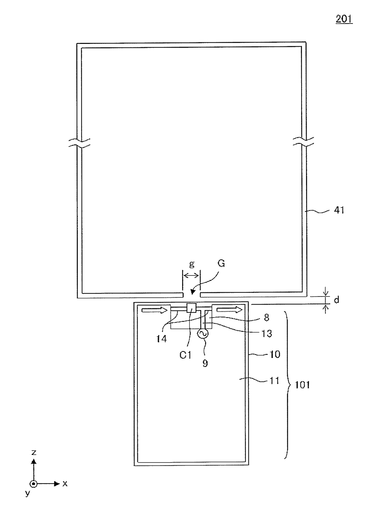
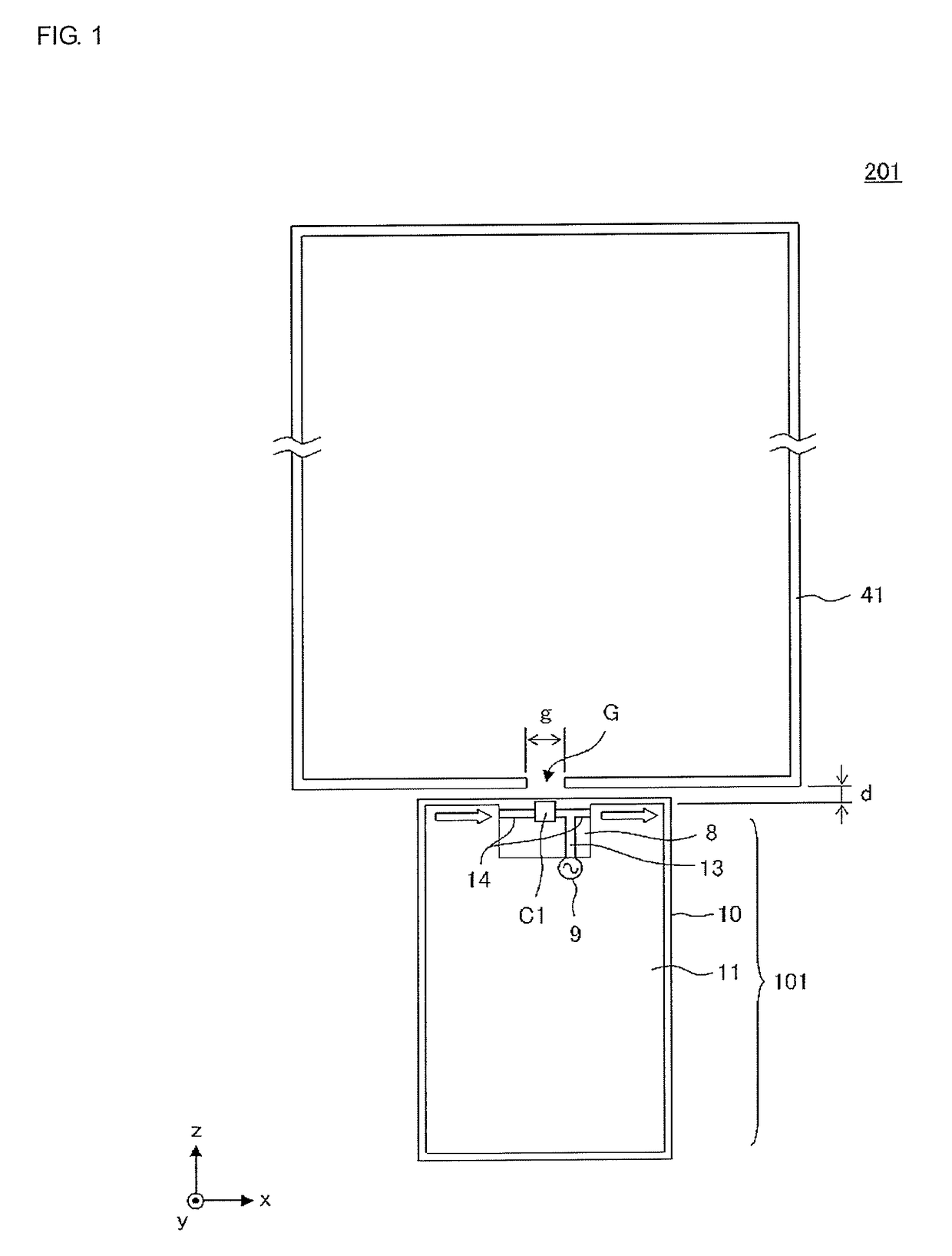
[0039]FIG. 1 is a diagram illustrating the principal constituent elements of an antenna device 201 according to a first embodiment. In FIG. 1, the antenna device 201 includes a communication module 101 and a loop-shaped conductor 41. The communication module 101 has a substrate 10 on which an approximately rectangular ground conductor 11 is formed. A non-ground region 8 is provided along one side of the ground conductor 11. A transmission line 13 and a radiation element 14 are formed in the non-ground region 8. Further, a capacitance element C1 is connected to the radiation element 14, and the transmission line 13 is connected to a feeding point of the radiation element 14. A feeder circuit 9 is provided on the substrate 10 and power is fed to the radiation element 14 by the feeder circuit 9 via the transmission line 13.
[0040]Feeding the power to the radiation elements 14 causes the radiation element 14 to resonate. A current is induced in the ground conductor 11 in the same manner ...
second embodiment
[0054]FIG. 7 is a diagram illustrating the principal constituent elements of an antenna device 202 according to a second embodiment. In FIG. 7, the antenna device 202 includes a communication module 102 and the loop-shaped conductor 41. The communication module 102 has the substrate 10 on which the approximately rectangular ground conductor 11 is formed. The non-ground region 8 is provided along one side of the ground conductor 11. A radiation element 15 is formed in the non-ground region 8. The feeder circuit 9 is provided on the substrate 10, and power is fed to the radiation element 15 by the feeder circuit 9. The radiation element 15 acts as a radiation element of a monopole antenna. Further, a portion near an open end of the radiation element 15 and an end portion EP1 of the loop-shaped conductor 41 which is near the gap G and is in the vicinity of the above portion of the radiation element 15, mainly form electric field coupling. Although intensity of electric field is weak in...
third embodiment
[0059]FIG. 10 is a diagram illustrating the principal constituent elements of an antenna device 203 according to a third embodiment. In FIG. 10, the antenna device 203 includes a communication module 103 and the loop-shaped conductor 41. The communication module 103 has the substrate 10 on which the approximately rectangular ground conductor 11 is formed. The non-ground region 8 is provided along one side of the ground conductor 11. Radiation elements 16a and 16b are formed in the non-ground region 8. The feeder circuit 9 is provided on the substrate 10, and the radiation element 16a is fed with power by the feeder circuit 9. The radiation element 16b is a non-power fed radiation element, and one end thereof is connected to the ground conductor 11 (grounded) while the other end is open. The open end of the radiation element 16b is near an open end of the radiation element 16a; the radiation element 16b is fed with power through capacitance generated between both the open ends. The r...
PUM
 Abstract
Description
Claims
Application Information
 - R&D
- Intellectual Property
- Life Sciences
- Materials
- Tech Scout
- Unparalleled Data Quality
- Higher Quality Content
- 60% Fewer Hallucinations
Browse by: Latest US Patents, China's latest patents, Technical Efficacy Thesaurus, Application Domain, Technology Topic, Popular Technical Reports.
© 2025 PatSnap. All rights reserved.Legal|Privacy policy|Modern Slavery Act Transparency Statement|Sitemap|About US| Contact US: help@patsnap.com


