Fuel cell and fuel cell stack comprising the same

a fuel cell and stack technology, applied in the direction of cell components, cell component details, electrochemical generators, etc., can solve the problems of deterioration of the membrane, insufficient reaction in the upstream portion of the reactant gas channel, etc., and achieve the effect of suppressing the degradation of the electrolyte layer

Active Publication Date: 2017-10-10
PANASONIC INTELLECTUAL PROPERTY MANAGEMENT CO LTD
View PDF29 Cites 0 Cited by
  • Summary
  • Abstract
  • Description
  • Claims
  • Application Information

AI Technical Summary

Benefits of technology

[0010]The present disclosure is directed to solving the above mentioned problems and an object of the present disclosure is to provide a fuel cell which is capable of suppressing degradation of an electrolyte layer (polymer electrolyte membrane) when a fuel cell, in particular, a polymer electrolyte fuel cell is operated under high-temperature and low-humidity conditions, and a fuel cell stack comprising the fuel cell.
[0015]To solve this, the fuel cell of the present disclosure is configured such that the gas permeation suppressing section is formed in the portion(s) of the first reactant gas channel and / or the second reactant gas channel which is / are formed in the first region and / or the second region. Therefore, it is possible to suppress the steam from moving from the region(s) of the electrode which face(s) the first region and / or the second region, to the first reactant gas channel and / or the second reactant gas channel formed in these regions. Thus, it is possible to suppress the electrode and hence the electrolyte layer from getting dried. As a result, degradation of the electrolyte layer (polymer electrolyte membrane) can be suppressed.
[0019]In such a configuration, it is possible to supply the reactant gas to the region(s) of the electrode which face(s) the first region and / or the second region while suppressing the steam from moving from the region(s) of the electrode which face(s) the first region and / or the second region, to the first reactant gas channel and / or the second reactant gas channel, which is / are formed in the region(s) of the electrode.
[0025]In such a configuration, it is possible to supply the reactant gas to the region(s) of the electrode which face(s) the first region and / or the second region while suppressing a steam from moving from the region(s) of the electrode which face(s) the first region and / or the second region, to the first reactant gas channel and / or the second reactant gas channel, which is / are formed in these region(s) of the electrode.
[0037]In such a configuration, it is possible to suppress the steam from moving from the regions of the electrode which face(s) the first region and / or the second region, to the first reactant gas channel and / or the second reactant gas channel, which are formed in these regions. This, it is possible to suppress the electrode and hence the electrolyte layer from getting dried. As a result, degradation of the electrolyte layer (polymer electrolyte membrane) can be suppressed.

Problems solved by technology

However, in the fuel cell disclosed in Patent document 1, if the fuel cell is operated under high-temperature and low-humidity conditions (e.g., the dew point of the reactant gas is set lower than the temperature of the interior of a fuel cell stack), the above reaction does not occur sufficiently in an upstream portion of the reactant gas channel.
As a result, water is not generated and a portion of the polymer electrolyte membrane which faces the upstream portion of the reactant gas channel gets dried, which results in deterioration of the membrane.

Method used


Image

  • Fuel cell and fuel cell stack comprising the same
  • Fuel cell and fuel cell stack comprising the same
  • Fuel cell and fuel cell stack comprising the same

Examples


embodiment 1

[0073][Configuration of Fuel Cell Stack]

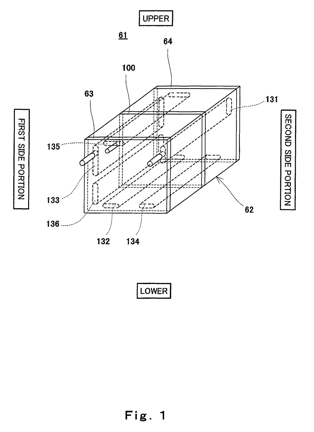
[0074]FIG. 1 is a perspective view schematically showing an exemplary configuration of a fuel cell stack according to Embodiment 1 of the present disclosure. In FIG. 1, the upper and lower sides of the fuel cell stack are expressed as the upper and lower sides in FIG. 1.

[0075]As shown in FIG. 1, a fuel cell stack 61 according to Embodiment 1 of the present disclosure includes a cell stack body 62 composed of polymer electrolyte fuel cells 100 (hereinafter simply referred to as fuel cells) which have a plate shape as a whole and are stacked together in a thickness direction thereof, first and second end plates 63 and 64 disposed at both ends of the cell stack body 62, and fastener members (not shown) fastening the cell stack body 62 to the first and second end plates 63 and 64, in a direction in which fuel cells 100 are stacked together. Although current collectors and insulating plates are provided at the first and second end plates 63 and 64,...

embodiment 2

[0154]FIG. 8 is a schematic view showing an exemplary configuration of the inner surface of a cathode separator of a fuel cell stack according to Embodiment 2 of the present disclosure. FIG. 9 is a schematic view showing an exemplary configuration of the inner surface of an anode separator of the fuel cell stack according to Embodiment 2 of the present disclosure. In FIG. 8, the upper and lower sides of the cathode separator are expressed as the upper and lower sides in FIG. 8 and a part of the fuel gas channel is indicated by imaginary lines. In FIG. 9, the upper and lower sides of the anode separator are expressed as the upper and lower sides in FIG. 9 and a part of the oxidizing gas channel is indicated by imaginary lines.

[0155]Referring to FIGS. 8 and 9, the fuel cell stack 61 (fuel cell 100) according to Embodiment 2 of the present disclosure has a configuration which is basically identical to that of the fuel cell stack 61 (fuel cell 100) of Embodiment 1 but is different from ...

embodiment 3

[0167]FIG. 10 is a schematic view showing an exemplary configuration of a cathode separator of a fuel cell stack (fuel cell) according to Embodiment 3 of the present disclosure. FIG. 11 is a schematic view showing an exemplary configuration of an anode separator of the fuel cell stack (fuel cell) according to Embodiment 3 of the present disclosure. In FIG. 10, the upper and lower sides of the cathode separator are expressed as the upper and lower sides in FIG. 10 and a part of the fuel gas channel is indicated by imaginary lines. In FIG. 11, the upper and lower sides of the anode separator are expressed as the upper and lower sides in FIG. 11 and a part of the oxidizing gas channel is indicated by imaginary lines.

[0168]Referring to FIGS. 10 and 11, the fuel cell stack 61 (fuel cell 100) according to Embodiment 3 of the present disclosure has a configuration which is basically identical to those of the fuel cell stacks 61 (fuel cells 100) of Embodiment 1 an Embodiment 2 but is differ...


PUM

PropertyMeasurementUnit
particle diameteraaaaaaaaaa

Abstract

A fuel cell of the present disclosure includes an electrolyte-layer-electrode assembly, a first separator, a second separator, and one or more gas permeation suppressing sections, the inner surface of the first separator and the inner surface of the second separator have a first region and a second region, the gas permeation suppressing section is provided at least one of a first reactant gas channel and a second reactant gas channel so as to overlap with the first region when viewed in a thickness direction of the first separator, and the gas permeation suppressing section is provided at least one of the first reactant gas channel and the second reactant gas channel so as to overlap with the second region when viewed in the thickness direction of the first separator.

Description

RELATED APPLICATIONS[0001]This application is the U.S. National Phase under 35 U.S.C. §371 of International Application No. PCT / JP2009 / 004605, filed on Sep. 15, 2009, which in turn claims the benefit of Japanese Application No. 2008-238825, filed on Sep. 18, 2008, the disclosures of which Applications are incorporated by reference herein.FIELD OF THE INVENTION[0002]The present disclosure relates to a configuration of a fuel cell and a configuration of a fuel cell stack comprising the fuel cell. Particularly, the present disclosure relates to a configuration of a polymer electrolyte fuel cell.DESCRIPTION OF THE RELATED ART[0003]Polymer electrolyte fuel cells (hereinafter referred to as PEFCs) are configured to generate electricity and heat simultaneously through an electrochemical reaction between a fuel gas containing hydrogen and an oxidizing gas containing oxygen, such as air.[0004]A cell of a PEFC includes a MEA (Membrane-Electrode-Assembly) composed of a polymer electrode membra...

Claims


Application Information

Patent Timeline
Patent Type & Authority Patents(United States)
IPC IPC(8): H01M8/24H01M8/02H01M8/0258H01M8/1007H01M8/0263
CPCH01M8/0258H01M8/1007H01M8/0263H01M8/0267H01M8/241H01M8/2483Y02E60/50
Inventor GEMBA, MIHOTSUJI, YOICHIRO
Owner PANASONIC INTELLECTUAL PROPERTY MANAGEMENT CO LTD
Why Eureka
Try Eureka