Sacroiliac joint implant system

a joint implant and sacroiliac joint technology, applied in the field of sacroiliac joint implant system, can solve the problems of removing painful degenerative aspects and providing stability of the joint while allowing a degree of motion remains unresolved, and achieve the effect of facilitating stabilization

Active Publication Date: 2017-10-17
JCBD
View PDF448 Cites 8 Cited by
  • Summary
  • Abstract
  • Description
  • Claims
  • Application Information

AI Technical Summary

Benefits of technology

[0010]Accordingly, a broad object of the invention can be to provide an inventive implant to facilitate stabilization while allowing an amount of motion of a sacroiliac joint. Embodiments of the sacroiliac joint implant can provide an elongate body, which can further include at least one fixation member, or a pair of fixation members which extend a distance outward from the longitudinal axis of the implant body adapted for non-transverse placement between the articular surfaces of the sacroiliac joint, and as to certain embodiments can further provide a third fixation member and additionally a fourth fixation member each adapted to extend a distance outward from the elongate body into the bone of the sacrum or the ilium.
[0011]Another broad object of the invention can be to provide an inventive method to facilitate stabilization of the sacroiliac joint while allowing an amount of motion utilizing particular embodiments of the inventive sacroiliac implant. Particular embodiments of the inventive method can include the steps of performing a minimally invasive posterior surgery that allows access to the posterior aspect of the sacroiliac joint. A sufficient portion of the articular cartilage or tissue between the articular surfaces of the sacroiliac joint can be removed to allow placement of particular embodiments of the inventive sacroiliac implant between surfaces of the sacroiliac joint. As to particular embodiments, a portion of the subcondral bone of the sacroiliac joint can be removed to provide an implant receiving space in the plane of the sacroiliac joint configured to allow interference fitting of the elongate member, or the elongate member with at least a first radial member between the opposed surfaces of the implant receiving space. The inventive method can further include the step of providing the implant receiving space with one or more radial member receiving channels cut into the bone (including one or more of the subchondral, cortical, or cancellous) and thereby locating one or more radial members in the bone of the sacrum or the bone of the ilium.
[0012]Another broad object of the invention can be to provide a surface capable of osseointegration having a configuration which allows the bone of the sacrum or ilium to grow into the implant to facilitate fixation of the implant to the sacrum or the ilium.
[0013]Another broad object of the invention can be to provide particular embodiments of the inventive sacroiliac implant with an amount of curvature along the length of the implant which allows placement of embodiments of the sacroiliac implant which have an increased surface area which remain within or substantially within the articular portion of the sacroiliac joint.
[0031]Disclosed herein is a method of treating a sacroiliac joint via implantation of an implant into a space of the sacroiliac joint. In one embodiment, the method includes: providing an iliac member including an interface surface and a fixation surface generally opposite the interface surface; providing a sacrum member including an interface surface and a fixation surface generally opposite the interface surface; delivering the iliac member into the sacroiliac joint space such that the fixation surface of the iliac member engages the ilium and the interface surface of the iliac member faces in the direction of the sacrum; delivering the sacrum member into the sacroiliac joint space such that the fixation surface of the sacrum member engages the sacrum and the interface surface of the sacrum member faces in the direction of the ilium; and engaging the interface surface of the iliac member with the interface surface of the sacrum member such that substantially restricted movement of the iliac member relative to the sacrum member is possible when both the iliac member and sacrum member are implanted in the sacroiliac joint space and the interface surfaces are engaged with each other.
[0037]Disclosed herein is a method of treating a sacroiliac joint via implantation of an implant into a space of the sacroiliac joint. In one embodiment, the method includes: positioning a generally empty balloon in the sacroiliac joint space; filling the positioned balloon with a curable biomaterial such that the balloon expands to fill at least a portion of the sacroiliac joint space to substantially restore a desired anatomy of the sacroiliac joint space; and allowing the biomaterial to cure. The cured biomaterial may exhibit elastic properties when submitted to forces present in the sacroiliac joint space.

Problems solved by technology

However, while each of these methods have been utilized for fixation and fusion of the sacroiliac joint over the past several decades, the methods to remove the painful degenerative aspects and to provide stability of the joint while allowing a degree of motion remains unresolved.

Method used


Image

  • Sacroiliac joint implant system
  • Sacroiliac joint implant system
  • Sacroiliac joint implant system

Examples


Embodiment Construction

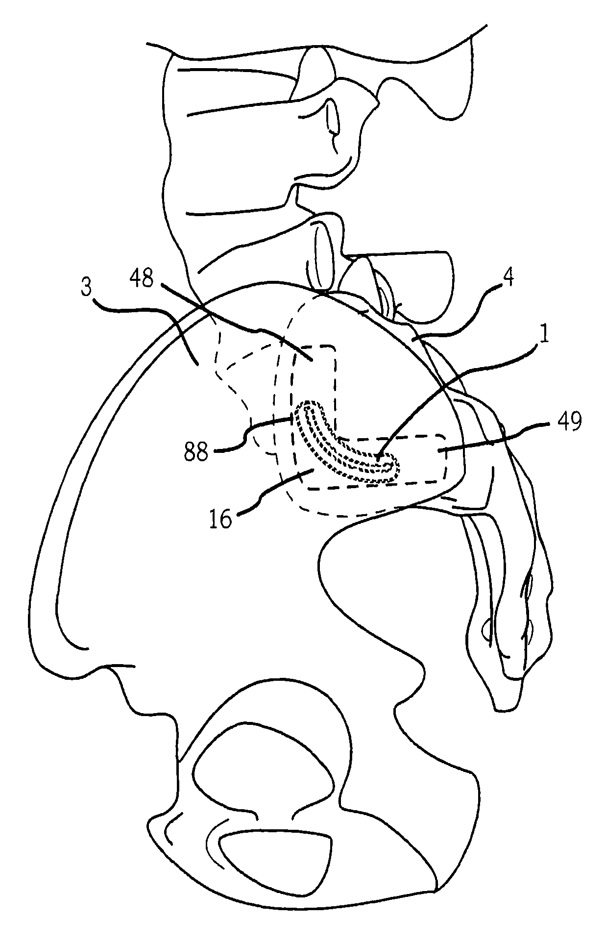
[0112]Generally, a sacroiliac joint implant system that provides embodiments of a sacroiliac joint implant and methods of placing the sacroiliac joint implant in relation to a sacroiliac joint to facilitate stabilization and allow an amount of motion of the sacroiliac joint.

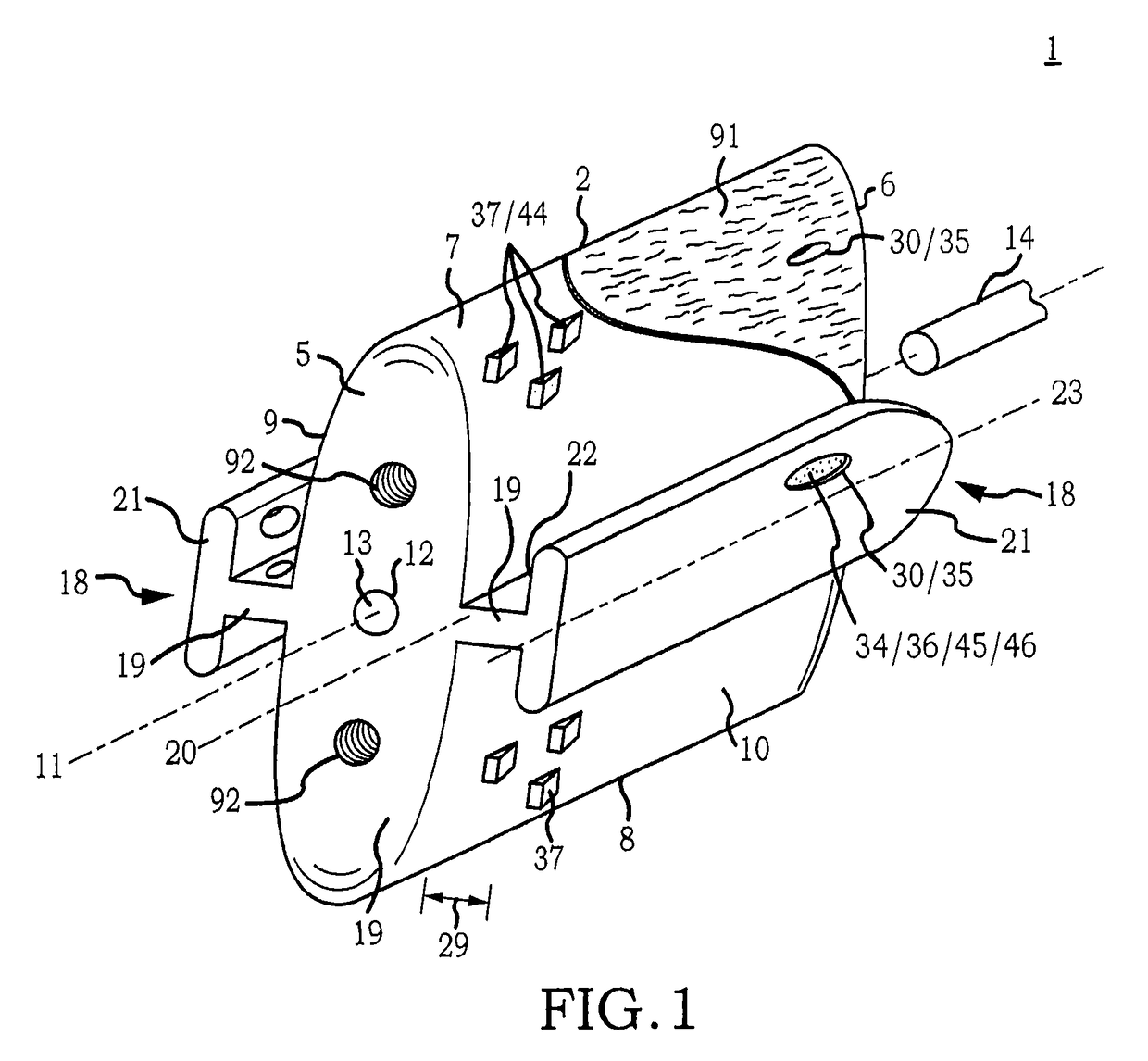
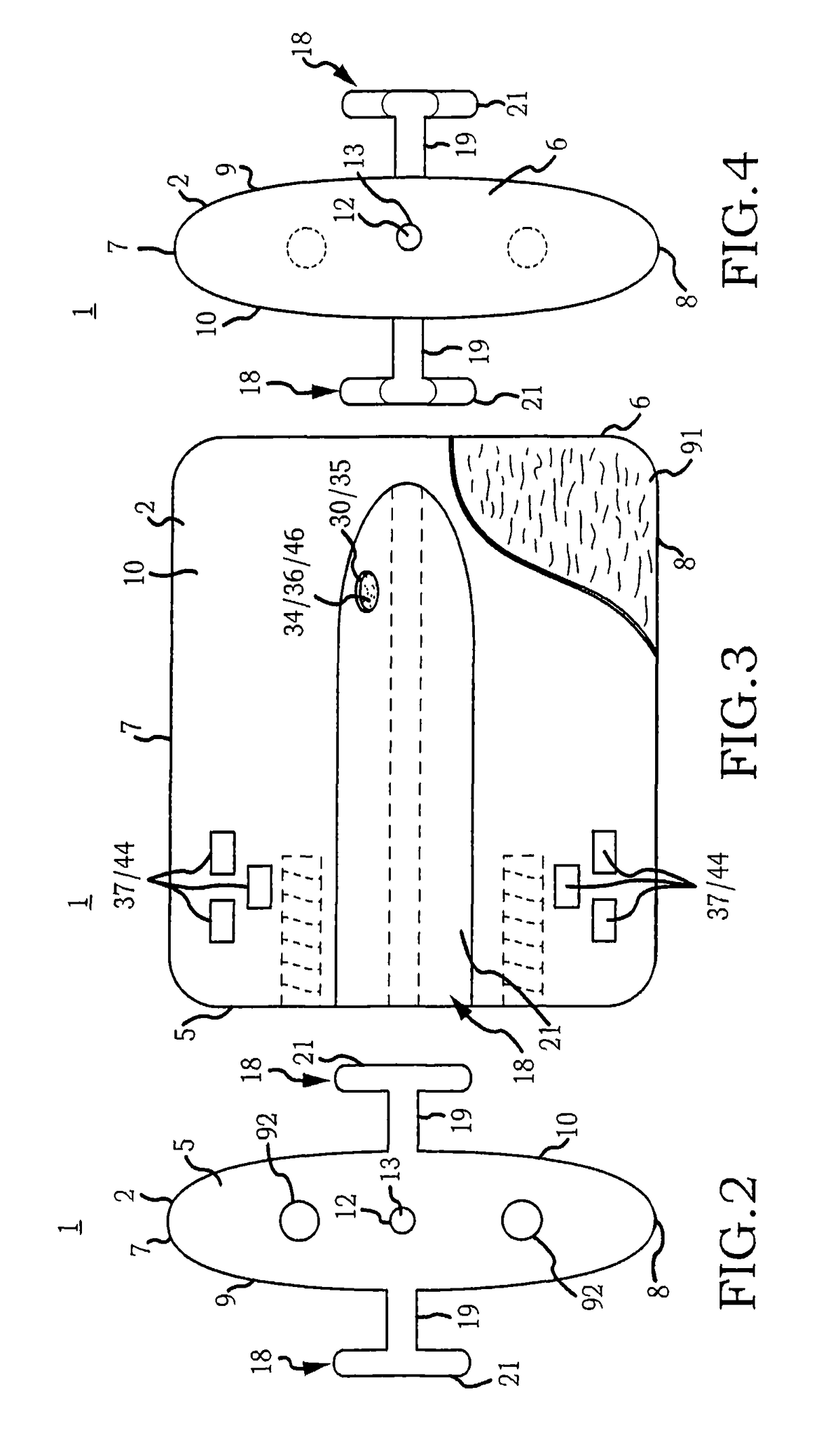
[0113]Now referring primarily to FIGS. 1-16, a non-limiting embodiment of an inventive sacroiliac joint implant (1) is shown which in part can include a first implant body (2). The first implant body (2) can have a generally rectangular configuration in plan view (see as a non-limiting example FIG. 3) and can have a generally oval or ellipsoidal configuration in end view (see as a non-limiting example FIGS. 42A-C). The first implant body (2) can have a configuration of sufficient dimensional relations to allow non-traverse placement between the surfaces of an ilium (3) and a sacrum (4) (see as non-limiting examples FIGS. 42A through 42C) and which avoid deformation under the normal forces of surgical placement an...


PUM


Abstract

Accordingly, a broad object of the invention can be to provide an inventive implant to facilitate stabilization while allowing an amount of motion of a sacroiliac joint. Embodiments of the sacroiliac joint implant can provide an elongate body, which can further include at least one fixation member, or a pair of fixation members which extend a distance outward from the longitudinal axis of the implant body adapted for non-transverse placement between the articular surfaces of the sacroiliac joint, and as to certain embodiments can further provide a third fixation member and additionally a fourth fixation member each adapted to extend a distance outward from the elongate body into the bone of the sacrum or the ilium.

Description

CROSS REFERENCE TO RELATED APPLICATIONS[0001]This Patent Cooperation Treaty (PCT) patent application claims priority to and the benefit of U.S. Provisional Patent Application 61 / 520,956, which is entitled “Sacroiliac Joint Implant System” and was filed Jun. 17, 2011.[0002]This PCT application is also a continuation-in-part (CIP) application of U.S. patent application Ser. No. 13 / 475,695 (“the '695 application”), which was filed May 18, 2012. The '695 application is a continuation-in-part (CIP) application of U.S. patent application Ser. No. 12 / 998,712 (“the '712 application”), which was filed May 23, 2011. The '712 application is the National Stage of International Patent Cooperation Treaty Patent Application PCT / US2011 / 000070 (“the '070 application”), which was filed Jan. 13, 2011. The '070 application claims the benefit of U.S. Provisional Patent Application 61 / 335,947, which was filed Jan. 13, 2010.[0003]The present application is also a continuation-in-part (CIP) application of ...

Claims


Application Information

Patent Timeline
Patent Type & Authority Patents(United States)
IPC IPC(8): A61F2/44A61B17/70A61F2/30
CPCA61F2/44A61B17/7055A61F2/30988A61F2002/30387A61F2002/30622A61F2002/30642A61F2002/30879A61F2002/30883A61F2002/30995A61B17/1626A61B17/1671A61B17/1739A61B17/1757A61B17/7043A61B17/7074A61B17/8645A61B2017/0046A61B2017/00876A61F2002/30179A61F2002/30331A61F2002/304A61F2002/30401A61F2002/30428A61F2002/30484A61F2002/305A61F2002/30507A61F2002/30579A61F2002/30601A61F2002/30774A61F2002/30828A61F2002/4687A61F2310/00017A61F2310/00023A61F2310/00179A61F2310/00359B33Y80/00A61F2/4603A61B17/025A61F2/4455A61F2/4611A61F2002/3055
Inventor DONNER, EDWARD JEFFREYDONNER, CHRISTOPHER THOMAS
Owner JCBD
Why Eureka
Try Eureka