
Combined shower with gravity switch mechanism

a technology of gravity switch and shower head, which is applied in the field of combined shower with gravity switch mechanism, can solve the problems of high manufactory cost, difficult to meet the needs of effective manufacturing, and difficult to meet the needs of effective manufacturing, and achieve the effect of convenient use and space saving of the prior art of combined shower, simple structure and convenient implementation

Active Publication Date: 2017-10-17
FUJIAN XIHE SANITARY WARE TECHNOLOGY CO LTD
View PDF6 Cites 0 Cited by
  • Summary
  • Abstract
  • Description
  • Claims
  • Application Information

AI Technical Summary

Benefits of technology

[0003]The object of the present invention is to overcome the technical problems of the existing technology, and the present invention provides a combined shower with gravity switch mechanism of simple structure and easy implement through the design of an attachment portion set on the handheld shower to be served as the gravity switch mechanism, so that it will accomplish function of switching only through the action of taking off the handheld shower or putting it away, is will make the control clear and simple for users during the operation.
[0007]In another preferred embodiment, wherein said gravity switch mechanism further comprises an elastic part which can preserve energy when the handheld shower attaches to the attachment portion, whereas release the preserved energy to urge the attachment portion reset to its original position when the handheld shower is detached from the attachment portion.
[0018]The combined shower with gravity switch mechanism of the present invention with simple structure and it is easy for implement, cause the sensing force of the attachment portion is changeable pending on the gravity of handheld shower applied or not, which will be identified by the user's action of taking off the handheld shower or hang it back, the attachment portion will be activated by its sensing force then drive the switching components work to trigger switch, it will make the switch function accomplished easily and clearly cause the handheld shower is taken as the controlling key element; The present invention achieves the function of controlling the diversion of waterway by the handheld shower's own gravity applied or not to trigger switch, on one hand, it's easy to operate and with high stability to take the handheld shower's own gravity as the switch key element, then it will avoid strength taking on hard pressing to trigger switch; on the other hand, it is easy to control and step-saving for switch test cause the result of water outlet will be consistent with the user's using intention either for wall-fixed shower or handheld shower, it's not necessary to waste time to recognize the water outlet come from which shower by controlling certain switch.

Problems solved by technology

There are many showers existing in the market including multi-functional combined shower such as combining handheld shower with fixed show like sunflower shower, spray head on the wall or swing shower, the function of water diversion is accomplished by handling switches of each shower mechanically, normally it should be designed with two switches respectively to control water inlet and select water outlet from one of the showers, therefore the user should shift the switches manually before the action of taking handheld shower from the rack, so that it will make the using process complex cause occupying two hands or two steps; meanwhile, there are some defects existing in prior art of combined showers: firstly, it needs two parts to accomplish the switching function then result in more complicated design of manufacturing structure and high manufactory cost; secondly, it takes big space to install necessary components on the wall of bathroom like switches for water inlet and outlet controlling as well as racks for hanging handheld shower or sunflower shower; thirdly, it's inclined to be confused in the using process of identifying the waterway switched by which shower before several times of trial and error; therefore, as can be seen from above, presently it is difficult to satisfy the needs for effective manufacturing, convenient usage and space saving of the prior art of combined shower.

Method used


Image

  • Combined shower with gravity switch mechanism
  • Combined shower with gravity switch mechanism
  • Combined shower with gravity switch mechanism

Examples


Embodiment Construction

[0028]The present invention will be further described with the drawings and the embodiments to make the present invention more clear and well-known. It should be noted that, the embodiments of the present invention is used to describe the present invention but not to limit the scope of the present invention.

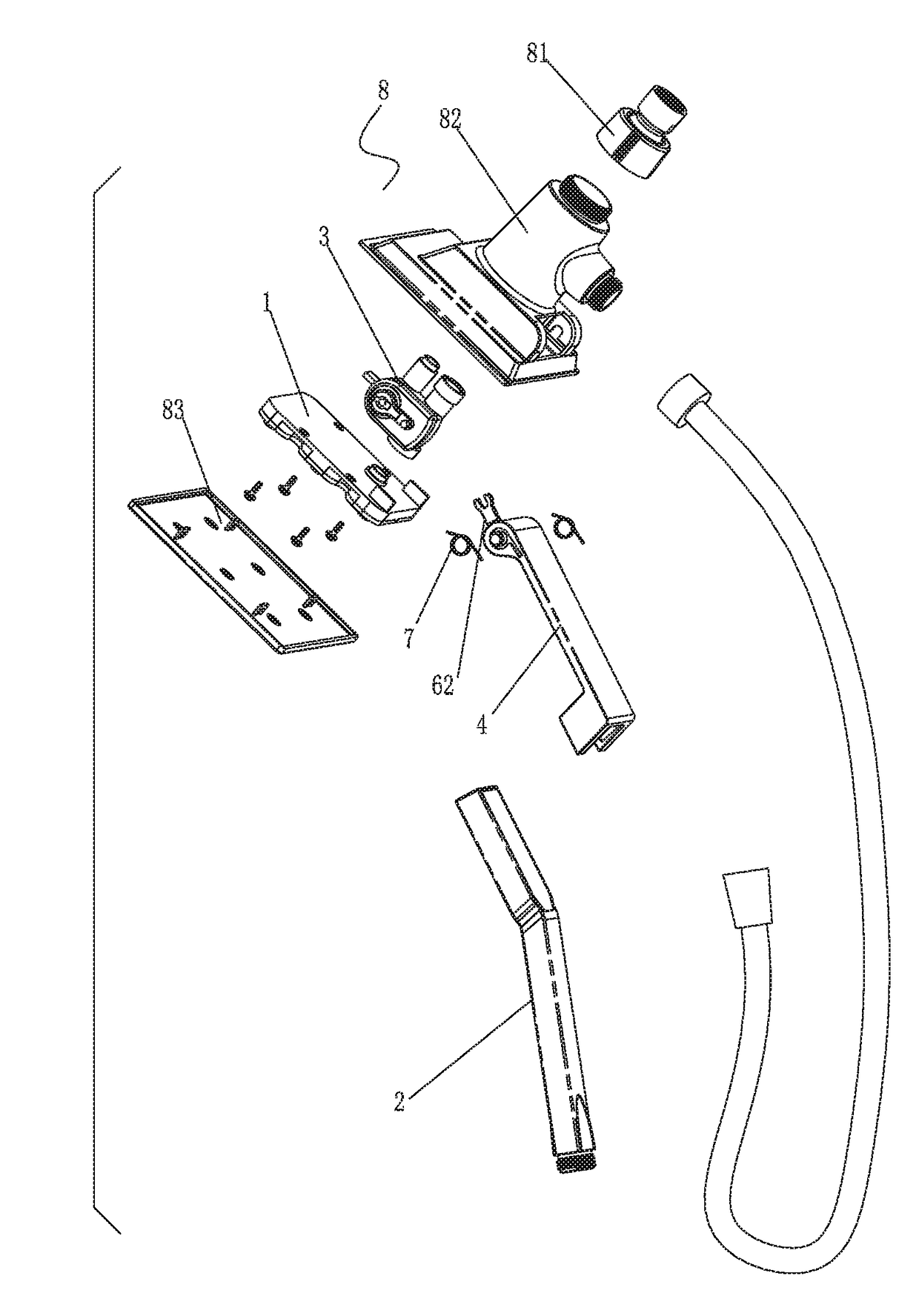
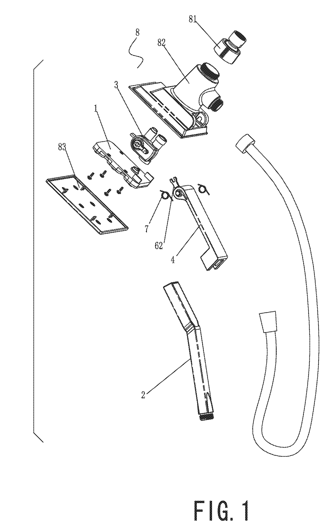
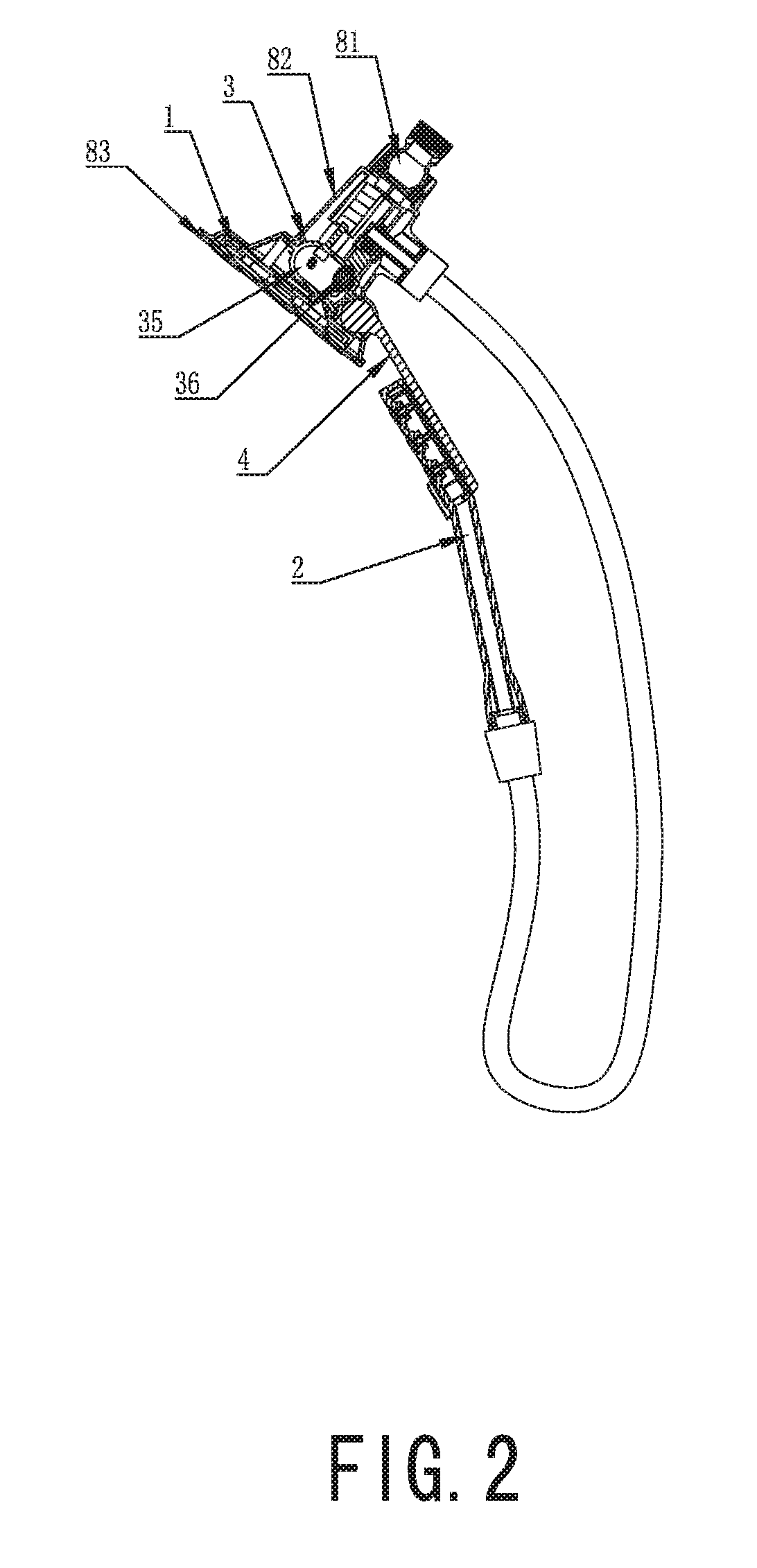
[0029]As figured in FIGS. 1˜3, a combined shower with gravity switch mechanism of the present invention comprises a wall-fixed shower 1, a handheld shower, a water diversion component 3 and a gravity switch mechanism 4 which is cooperated to the water diversion component 3.

[0030]The water diversion component 3 comprises a water inlet 30 and two water outlets 31 / 32 that are respectively connected to the wall-fixed shower 1 and the handheld shower; the water diversion component 3 comprises an upper sleeve 33, a lower sleeve 34 and a switching component, the switching component comprises a switching shaft 5. The upper sleeve 33 and the lower sleeve 34 which are connected to each oth...


PUM


Abstract

A combined shower with a gravity switch mechanism includes a wall-fixed shower, a handheld shower and a water diversion component, the water diversion component includes a water inlet, two water outlets respectively connected to the wall-fixed shower and handheld shower, and a switching component which is used to switch the waterway communication between the water inlet and two water outlets. The shower also includes a gravity switch mechanism and an attachment portion. The attachment portion interacts with the switching component to drive the activation of the switching component to trigger the switch to make the handheld shower activate or remain static relative to the position of the wall-fixed shower.

Description

FIELD OF THE INVENTION[0001]The present invention relates to sanitary wares, especially to a combined shower with gravity switch mechanism.BACKGROUND OF THE INVENTION[0002]There are many showers existing in the market including multi-functional combined shower such as combining handheld shower with fixed show like sunflower shower, spray head on the wall or swing shower, the function of water diversion is accomplished by handling switches of each shower mechanically, normally it should be designed with two switches respectively to control water inlet and select water outlet from one of the showers, therefore the user should shift the switches manually before the action of taking handheld shower from the rack, so that it will make the using process complex cause occupying two hands or two steps; meanwhile, there are some defects existing in prior art of combined showers: firstly, it needs two parts to accomplish the switching function then result in more complicated design of manufac...

Claims


Application Information

Patent Timeline
Patent Type & Authority Patents(United States)
IPC IPC(8): E03C1/04B05B1/30B05B1/18
CPCE03C1/0408B05B1/18B05B1/30
Inventor LIN, XIAOFALIN, XIAOSHANLIU, QIQIAODENG, XIAOQINGXU, JUN
Owner FUJIAN XIHE SANITARY WARE TECHNOLOGY CO LTD
Learn More