
Twin tube damper with remote gas reservoir

a technology of gas reservoir and damper, which is applied in the direction of shock absorbers, cycle equipment, cycles, etc., can solve the problems of inability to adapt, physical size of fluid volume, and rapid increas

Active Publication Date: 2017-10-24
FOX FACTORY
View PDF11 Cites 2 Cited by
  • Summary
  • Abstract
  • Description
  • Claims
  • Application Information

AI Technical Summary

Benefits of technology

The patent describes a fluid damper with two volumes that can communicate with each other and a gas reservoir. The damper has valves that can open or close the communication between the gas reservoir and the compression and rebound volumes. The valves are opened or closed based on the difference in pressure across them, and the size of the pathway between the compression and rebound volumes can change as the piston moves. The technical effect of this design is that it allows for independent control of the compression and rebound volume communication with the gas reservoir, and provides a variable size pathway for optimal performance of the damper.

Problems solved by technology

The fluid flow restriction elements, because they are located on the piston which is sealed within the housing, are typically not user adjustable, and are also typically preset for “average” use conditions and thus are not adaptable to varying conditions.
During a compression event, the physical size of the fluid volume on the rebound side of the piston may rapidly increase, and if the fluid flow rate into the rebound chamber is not sufficiently fast, the pressure will drop in the fluid on the rebound side of the chamber to a level where any gas, such as air, entrained in the fluid will aspirate to reform a gas state thereof, causing cavitation in the fluid.
This can cause serious disruption in the proper operation of the damper, and unacceptable noise emanating from the damper.

Method used


Image

  • Twin tube damper with remote gas reservoir
  • Twin tube damper with remote gas reservoir
  • Twin tube damper with remote gas reservoir

Examples


Embodiment Construction

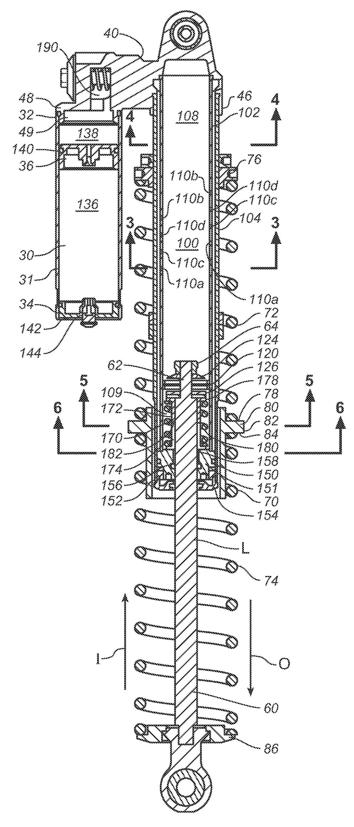
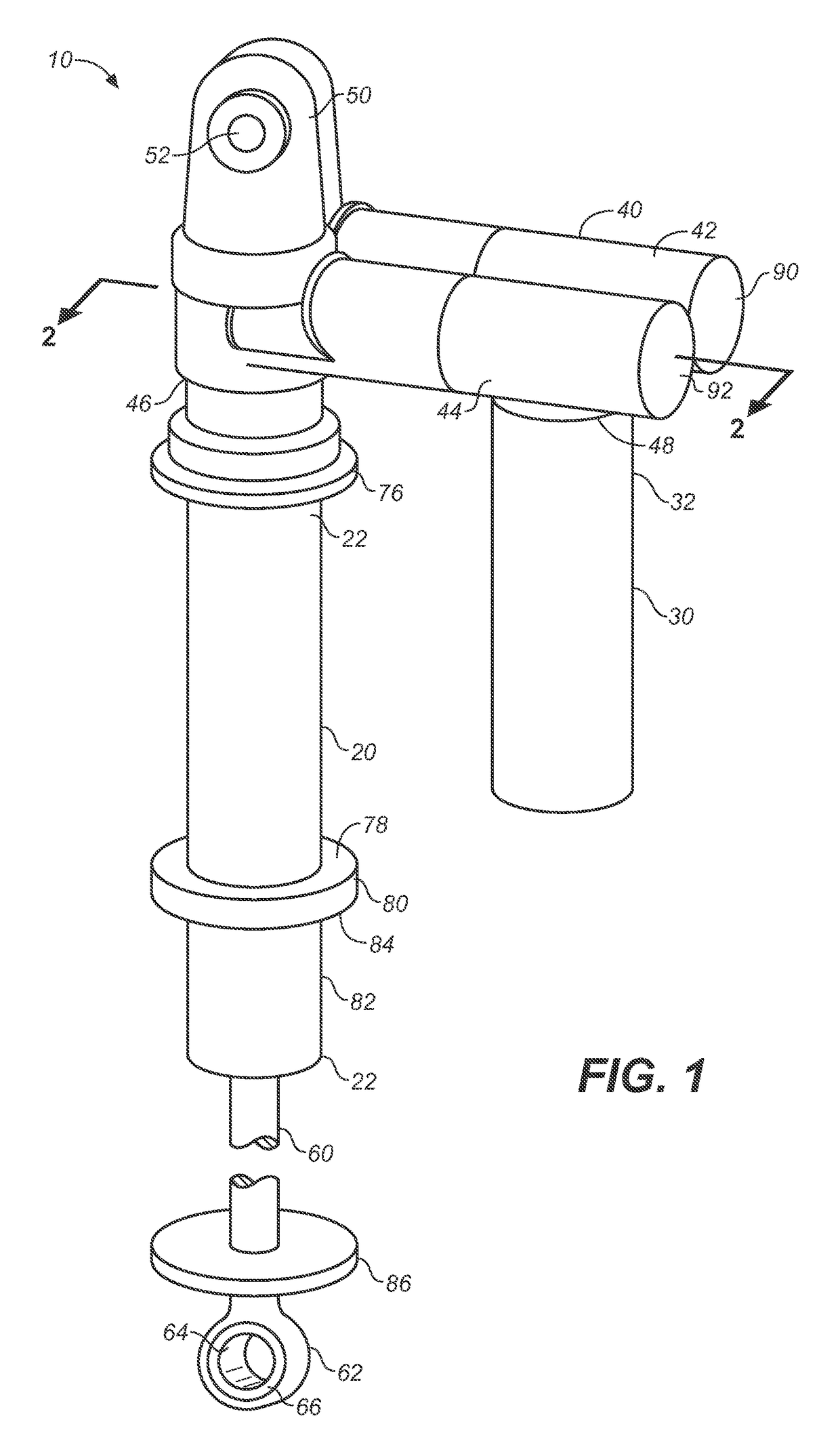
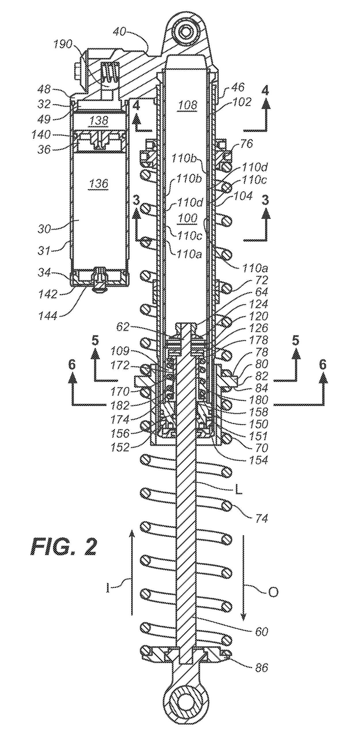
[0029]A dampening device, such as a strut or shock absorber, generally includes a tube shaped housing within which a piston, disposed on an end of a piston rod which extends outwardly of the housing, moves in response to forces imposed on the housing and the rod, the movement dampened by the presence of a fluid in the housing passing through valved openings in the piston, a secondary reservoir fluidly connected to the tube, and a connecting portion interconnecting the fluid portion f the tube and the secondary reservoir. Fluid is enabled to move between the housing and the secondary reservoir, in response to movement of the piston inwardly and outwardly of the housing. Fluid on one side of the piston is able to move through the piston, to the fluid volume on the opposite side of the piston, through one or more check valves within the body of the piston. The rate of fluid flow between the fluid volumes on either side of the piston, and between the fluid volumes in the dampening membe...


PUM


Abstract

A damper is provided having a twin tube construction interconnected to a gas reservoir. The connection of each of the inner and outer volumes of the twin tube to the gas reservoir is independently valved, and each of these valves are independently settable to change the differential pressure thereacross at which they open. The damper provides flow passages directly from the inner and outer volumes to enable flow form the compression to rebound sides thereof, as well as through the valved connections to the gas reservoir and at least one valved opening in the damper piston.

Description

CROSS-REFERENCE TO RELATED APPLICATIONS[0001]This application claims the benefit of and claims priority to the U.S. Provisional Patent Application No. 61 / 978,620 filed on Apr. 11, 2014, entitled “TWIN TUBE DAMPER WITH REMOTE GAS RESERVOIR” by Christopher Paul Cox, assigned to the assignee of the present application, and is hereby incorporated by reference in its entirety.BACKGROUND OF THE INVENTION[0002]Field of the Invention[0003]The present disclosure relates to the field of dampening devices for vehicles, such as bicycles, motorcycles and four or greater wheeled vehicles. In a further aspect, the disclosure relates to fluid dampers having lower incidence of cavitation and predictable and user variable, separate, compression and rebound characteristics.[0004]Description of Related Art[0005]Vehicle suspension systems typically include a spring component or components and a damping component or components. Typically, mechanical springs, such as metal leaf or helical springs, have be...

Claims


Application Information

Patent Timeline
Patent Type & Authority Patents(United States)
IPC IPC(8): B60G13/06B62K25/04
CPCB60G13/06B62K25/04B60G2500/10B60G2300/12B60G2202/24F16F9/065
Inventor COX, CHRISTOPHER PAUL
Owner FOX FACTORY
Learn More