Vehicle detector with improved loop oscillator circuit

Active Publication Date: 2017-10-24
RENO A&E
View PDF4 Cites 2 Cited by
  • Summary
  • Abstract
  • Description
  • Claims
  • Application Information

AI Technical Summary

Benefits of technology

The invention is a device that detects vehicles using an oscillator circuit. It has a control input terminal to activate or deactivate the device, an output terminal to show the results, and a circuit to maintain the amplitude of the output signals within a certain range. When the device is turned off, it has a circuit to stop any ringing or noise in the output signals. The device is simple and inexpensive, with just a few additional components needed to function.

Problems solved by technology

While the oscillator components and the transformer can be mounted to a circuit board housed within a control unit cabinet and thereby somewhat shielded from the outside environment, the loop and the interconnecting electrical conductors of necessity are directly exposed to the outside environment and consequently are directly subject to changes in environmental conditions, such as wide variations in temperature and humidity, as well as mechanical vibrations due to vehicle traffic, construction work, seismic earth movements and the like.
More particularly, changes in environmental conditions can adversely affect the amplitude of the loop oscillator circuit to such an extent that one or more loop cycles can be missed by the loop counter, or one or more phantom loop cycles can be erroneously counted by the loop counter.
In either case, the resulting accumulated sample count will not accurately reflect whether or not the status of the loop circuit has actually changed, and the vehicle detector may erroneously generate a false Call signal or erroneously drop an existing Call signal.
Known vehicle detector oscillator circuits are not designed to compensate for this severe disadvantage.
Known vehicle detector oscillator circuits suffer from an additional disadvantage.
This “ringing” phenomenon can carry over to the oscillator circuits in adjacent vehicle lanes by virtue of cross-talk between the ringing oscillator circuit and the adjacent lane oscillator circuits, which interferes with their operation and can cause erroneous results in those signals.

Method used


Image

  • Vehicle detector with improved loop oscillator circuit
  • Vehicle detector with improved loop oscillator circuit
  • Vehicle detector with improved loop oscillator circuit

Examples


Embodiment Construction

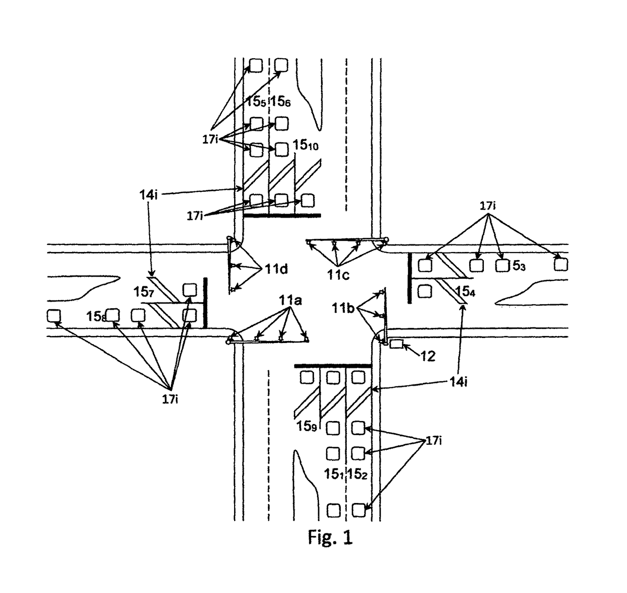
[0021]Turning now to the drawings, FIG. 1 is a schematic aerial view of a controlled 4-way vehicle traffic intersection. The intersection is provided with four sets of control heads 11a-11d each containing the usual traffic lights for providing red, amber, and green traffic control signals for oncoming vehicles. The operation of each set of control heads is under the supervision of a standard traffic controller 12 mounted in a cabinet located at a convenient intersection location. The traffic controller 12 has a plurality of output circuits for driving the individual traffic lights comprising each set of control heads 11a-11d. A plurality of vehicle detectors (not illustrated) is located in the same cabinet as traffic controller 12 and each vehicle detector provides motorized vehicle CALL signals to traffic controller 12 in the manner described below. Each vehicle detector is coupled to one or more vehicle detector loops 14i located in the various lanes leading to the intersection. ...


PUM


Abstract

An oscillator unit for a vehicle detector includes an oscillator circuit for generating vehicle detector loop signals in response to enabling control signals from a vehicle detector control unit, a gain control circuit for maintaining the amplitude of the oscillator output signals within a limited range, and a clamping circuit for eliminating ringing of the oscillator output signals when operation of the oscillator circuit is disabled. The gain control circuit eliminates random amplitude changes in the vehicle detector loop signals generated by the oscillator circuit caused by changing environmental conditions experienced by the vehicle detector loop. The clamping circuit provides immediate clamping of the oscillator circuit operation to eliminate ringing when the control signal switches to the off state. The few additional circuit components which provide the gain control and clamping functions add very little to the overall cost of the oscillator circuit.

Description

BACKGROUND OF THE INVENTION[0001]This invention relates to vehicle detector systems used to detect the presence or absence of a motor vehicle over an inductive loop embedded in the pavement. More particularly, this invention relates to a vehicle detector system with an improved loop oscillator circuit[0002]Vehicle detectors have been used for a substantial period of time to generate information specifying the presence or absence of a vehicle at a particular location sometimes termed a detection zone. Such detectors have been used at intersections, for example, to supply information used by an associated traffic control unit to control the operation of the traffic signal heads, and have also been used to supply control information used in conjunction with automatic entrance and exit gates in parking lots, garages and buildings. A widely used type of vehicle detector employs the principle of period shift measurement in order to determine the presence or absence of a vehicle in or adja...

Claims


Application Information

Patent Timeline
IPC IPC(8): G08G1/042H03B5/24H03K5/08H03G1/00
CPCG08G1/042H03B5/24H03K5/08H03G1/0029H03B5/1228G08G1/08H03B5/1203H03B2200/0062H03B5/1265
Inventor POTTER, THOMAS RAY
Owner RENO A&E
Why Eureka
Try Eureka