
Projector and method of controlling projector

a projector and projector technology, applied in the field of projectors, can solve problems such as increasing processing load, and achieve the effect of suppressing the increase in processing load

Active Publication Date: 2017-10-31
SEIKO EPSON CORP
View PDF7 Cites 0 Cited by
  • Summary
  • Abstract
  • Description
  • Claims
  • Application Information

AI Technical Summary

Benefits of technology

This patent describes a system that uses a projector to perform processing based on a captured image. The system can adjust the image-capturing resolution to achieve high-accuracy processing, while also reducing the processing load. This allows for precise correction of distortion or other image issues with minimal impact on the processing system. Overall, the system improves processing efficiency and accuracy while controlling processing load.

Problems solved by technology

However, since an amount of data of the captured images increases, a processing load increases.

Method used


Image

  • Projector and method of controlling projector
  • Projector and method of controlling projector
  • Projector and method of controlling projector

Examples


Embodiment Construction

[0025]Hereinafter, an embodiment to which the present invention is applied will be described with reference to the attached drawings.

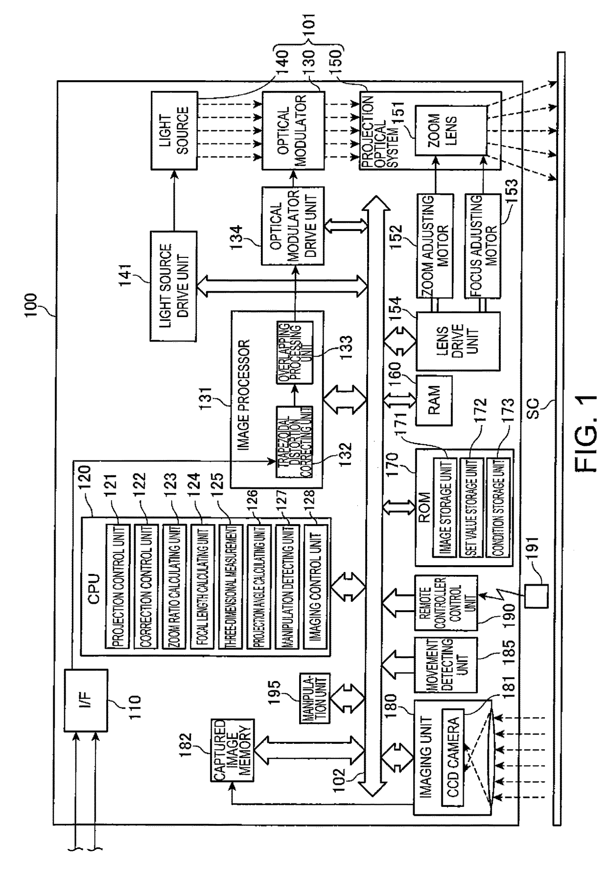
[0026]FIG. 1 is a block diagram illustrating an overall configuration of a projector 100 according to this embodiment. The projector 100 projects an image onto a screen SC (projection surface) on the basis of image data that is stored in a built-in image storage unit 171. In addition, the projector 100 may project an image onto the screen SC on the basis of image data that is input from an external image supply device (not shown) such as a personal computer and various video players. The image data may be moving picture (video) data or still image data.

[0027]In this embodiment, a configuration in which the projector 100 performs front surface projection with respect to the screen SC provided with a reflection curtain is exemplified. The screen SC stands substantially upright, and a screen surface has a rectangular shape. In addition, as the projection ...


PUM


Abstract

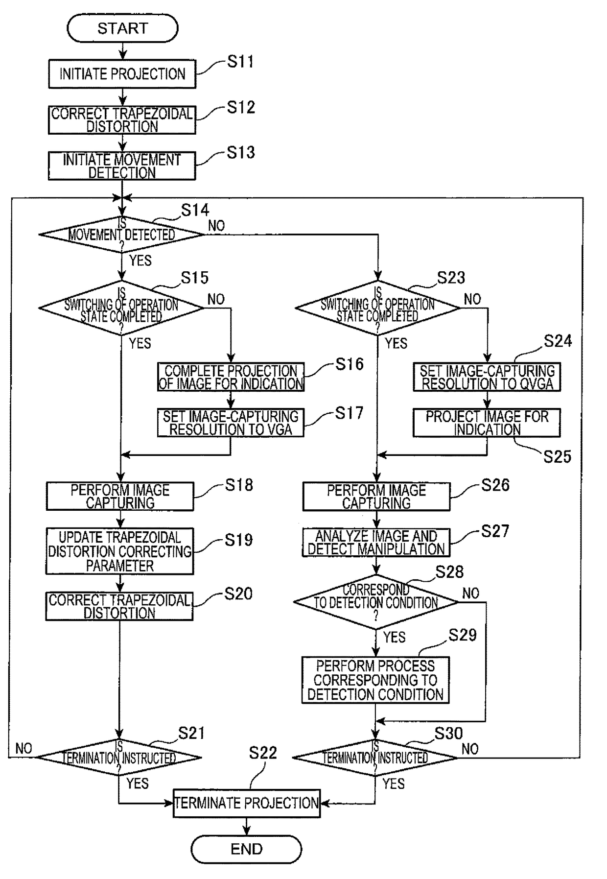
A projector includes a manipulation detecting unit that performs a manipulation detecting process on the basis of captured image data of an imaging unit, and a correction control unit that performs a distortion correcting process on the basis of the captured image data. An imaging control unit sets an image-capturing resolution of the imaging unit to resolutions different from each other between a case where the manipulation detecting unit performs the manipulation detection process and a case where the correction control unit performs the distortion correcting process.

Description

[0001]The entire disclosure of Japanese Patent Application No. 2013-239537, filed Nov. 20, 2013 is expressly incorporated by reference herein.BACKGROUND[0002]1. Technical Field[0003]The present invention relates to a projector that projects an image on a projection surface, and a method of controlling a projector.[0004]2. Related Art[0005]In the related art, in projectors that project an image onto a projection surface, a projector that captures a projected image is known (for example, refer to JP-A-2009-64110). For example, a device described in JP-A-2009-64110 detects a manipulation of the projected image by performing a process of extracting a difference between a plurality of captured images.[0006]In a case of performing the detection of the manipulation and the like on the basis of the captured images, if a resolution is increased, a minute variation in an image-capturing range can be detected, and thus high-accuracy processing can be performed. However, since an amount of data...

Claims


Application Information

Patent Timeline
Patent Type & Authority Patents(United States)
IPC IPC(8): G09G5/00G03B21/14G03B21/26
CPCG03B21/14G03B2206/00G03B21/26G03B21/147
Inventor ICHIEDA, HIROYUKI
Owner SEIKO EPSON CORP
Learn More