Circuit for and method of receiving an input signal

a technology of input signal and circuit, applied in the field of data receivers, can solve the problems of consuming additional power, amplitude of signal heavily attenuated, and signal already small for high loss channels, and achieve the effect of high frequency gain

Active Publication Date: 2017-10-31
XILINX INC
View PDF5 Cites 19 Cited by
  • Summary
  • Abstract
  • Description
  • Claims
  • Application Information

AI Technical Summary

Benefits of technology

[0005]A method of receiving an input signal is also described. The method comprises receiving a differential input signal; configuring a continuous time linear equalizer to receive a first signal of the differential input signal at a first equalizer input of a first equalizer path and a second signal of the differential input signal at a second equalizer input of a second equalizer path, programming a first programmable load capacitor coupled to a first equalizer path output the continuous time linear equalizer and a second programmable load capacitor coupled to a second equalizer path output; and programming a programmable source capacitor coupled between the first equalizer path and the second equalizer path; providing a high frequency gain boost with a fixed DC gain; and coupling an output to first and second outputs of the continuous time linear equalizer.

Problems solved by technology

However, with a conventional CTLE design, the amplitude of the signal is heavily attenuated.
In many cases, the signal is already small for high loss channels.
However, the additional gain requirement in the AGC stage can consume additional power, which is not desirable.

Method used


Image

  • Circuit for and method of receiving an input signal
  • Circuit for and method of receiving an input signal
  • Circuit for and method of receiving an input signal

Examples


Embodiment Construction

[0015]While the specification includes claims defining the features of one or more implementations of the invention that are regarded as novel, it is believed that the circuits and methods will be better understood from a consideration of the description in conjunction with the drawings. While various circuits and methods are disclosed, it is to be understood that the circuits and methods are merely exemplary of the inventive arrangements, which can be embodied in various forms. Therefore, specific structural and functional details disclosed within this specification are not to be interpreted as limiting, but merely as a basis for the claims and as a representative basis for teaching one skilled in the art to variously employ the inventive arrangements in virtually any appropriately detailed structure. Further, the terms and phrases used herein are not intended to be limiting, but rather to provide an understandable description of the circuits and methods.

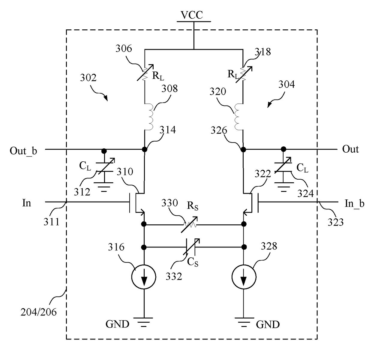
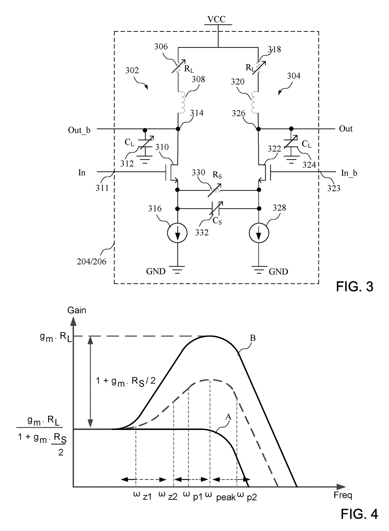
[0016]A continuous-time lin...


PUM


Abstract

A continuous time linear equalizer comprises an input of a first equalizer path configured to receive a first differential input signal; an input of a second equalizer path configured to receive a second differential input signal; a first programmable load capacitor coupled to an output of the first equalizer path; a second programmable load capacitor coupled to an output of the second equalizer path; and a programmable source capacitor coupled between the first equalizer path and the second equalizer path.

Description

FIELD OF THE INVENTION[0001]The present invention relates generally to data receivers, and in particular, to a circuit for and a method of receiving an input signal.BACKGROUND OF THE INVENTION[0002]Data transmission is an important aspect of integrated circuit devices. A continuous time linear equalizer (CTLE) may be necessary to receive data, particularly high speed data. Existing CTLE designs for high frequency equalization relies on degeneration resistance to change the amount of relative high-frequency boost. For higher loss channels, more equalization is needed. However, with a conventional CTLE design, the amplitude of the signal is heavily attenuated. In many cases, the signal is already small for high loss channels. This loss in amplitude has to be compensated in a conventional device by requiring more gain from a following Automatic Gain Control (AGC) stage. However, the additional gain requirement in the AGC stage can consume additional power, which is not desirable.[0003]...

Claims


Application Information

Patent Timeline
Patent Type & Authority Patents(United States)
IPC IPC(8): H03B5/06H04L25/03H03G3/30H04B1/10H03B5/36
CPCH04L25/03019H04B1/10H03G3/3036H03B5/06H03B2200/005H03B5/366H03B2200/0062H04L25/03885
Inventor ELZEFTAWI, MOHAMED N.ZHANG, HONGTAO
Owner XILINX INC
Why Eureka
Try Eureka