Telescopic material conveyer apparatus

a conveyer and material technology, applied in the field of construction, can solve the problems of cranes being very expensive to operate, workers being injured, and requiring a more highly skilled sta

Active Publication Date: 2017-10-26
CLEASBY LLC
View PDF9 Cites 3 Cited by
  • Summary
  • Abstract
  • Description
  • Claims
  • Application Information

AI Technical Summary

Benefits of technology

[0014]In one embodiment, the connecting hardware includes a push bar assembly of two elongate and parallel bars held in position by one or more cross frame members, wherein one or both push bars of the assembly are connected to one or more than one drive chain and sprocket the drive chain caused to advance or retard via one or more chain-drive gears having connection to a matching gear or gears on the hydraulic motor. In one embodiment, the roller assemblies include an upper rear roller assembly and a lower front roller assembly, both assemblies in contact with the extension boom, the roller assemblies each including two or more pivot axles for enabling the individual rollers or roller sets to adopt position to conform to load pressure and load balance differences exerted on the extension boom.
[0017]In one embodiment, the safety valve is electronically connected to the load sensor integrated with the lift mechanism. In one embodiment, the material conveyer apparatus further includes a boom support leg having an interfacing foot that rests on the rooftop, the support leg reducing load pressure on the lift cylinder. In one embodiment, the main boom tapers down at the rear by approximately 15 degrees off of horizontal reducing the vertical height requirement for loading materials on the material conveyer apparatus. In one embodiment, a remote control is provided for starting and stopping the conveyer belt, the remote control integrated in operation with the at least one hydraulic safety valve and associated load sensor, the remote becoming non-operational to start the conveyor belt if it is stopped due to load sensor data.

Problems solved by technology

This caused injuries to workers.
Another problem in the art is that customers want to be able to transfer materials to a least a 50′ foot height and be able to do that in tight and congested areas where their buildings were located.
Cranes are very expensive to operate and require a more highly skilled staff to operate as opposed to a conveyor.
The inventors built several 40′ conveyors which had to be mounted on semi trailers which are very hard to maneuver in tight and congested areas and therefore the answer to the problem has not yet been addressed.
It is critical that regular maintenance is conducted on a boom assisted conveyor such as the one referenced above due in part to complexity of operation of the hydraulic components and controls for raising lowering and positioning the boom for materials delivery and return from a rooftop.
Such heavy material loads on the conveyor may cause friction wear to components disposed at the upper end of the boom structure when the material is offloaded while the conveyor is running.
This causes the wearing off of protective non-conductive coatings applied to certain components of the system of Frye et al, such components including metal such as the conveyor lugs, certain drive components (chain, sprocket), and other structural belt support components.
The above system is liable to produce a static shock during operation of the conveyor to move materials, such shock released when operators come to close to a worn portion of the boom structure or to any of the above mentioned components.

Method used


Image

  • Telescopic material conveyer apparatus
  • Telescopic material conveyer apparatus
  • Telescopic material conveyer apparatus

Examples


Embodiment Construction

[0049]In various embodiments described in enabling detail herein, the inventors provide a relatively frictionless substantially nonconductive conveyor apparatus adaptable to a hydraulically-operated boom structure that reduces static buildup of electricity during conveyor operation and reduces frictional wear on one or more components of the conveyor apparatus including the conveyor belt. The present invention is described in enabling detail using the following examples, which may describe more than one relevant embodiment falling within the scope of the present invention.

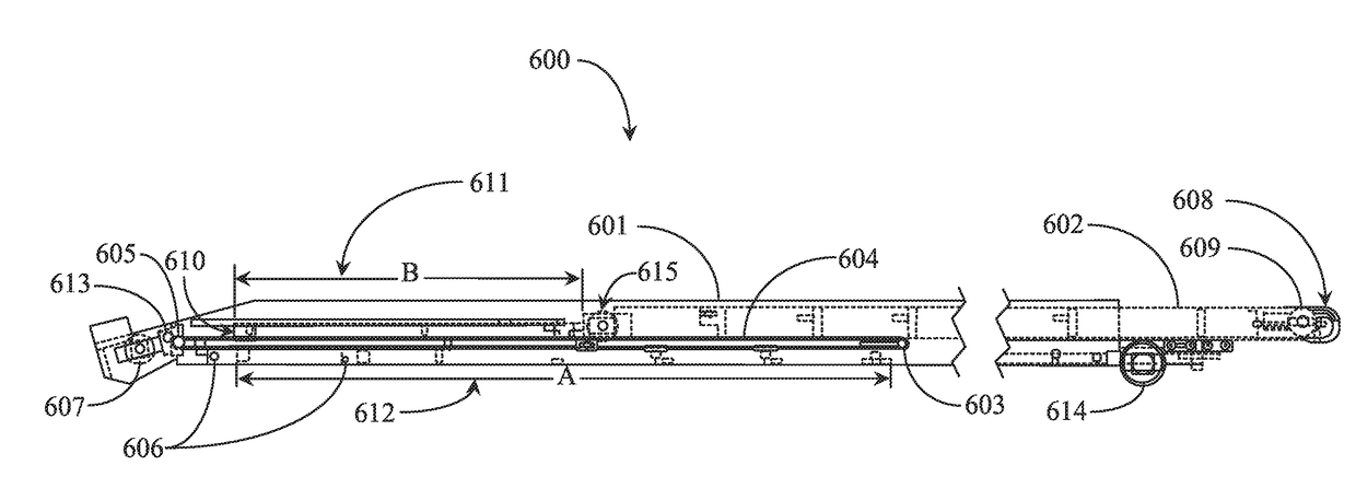
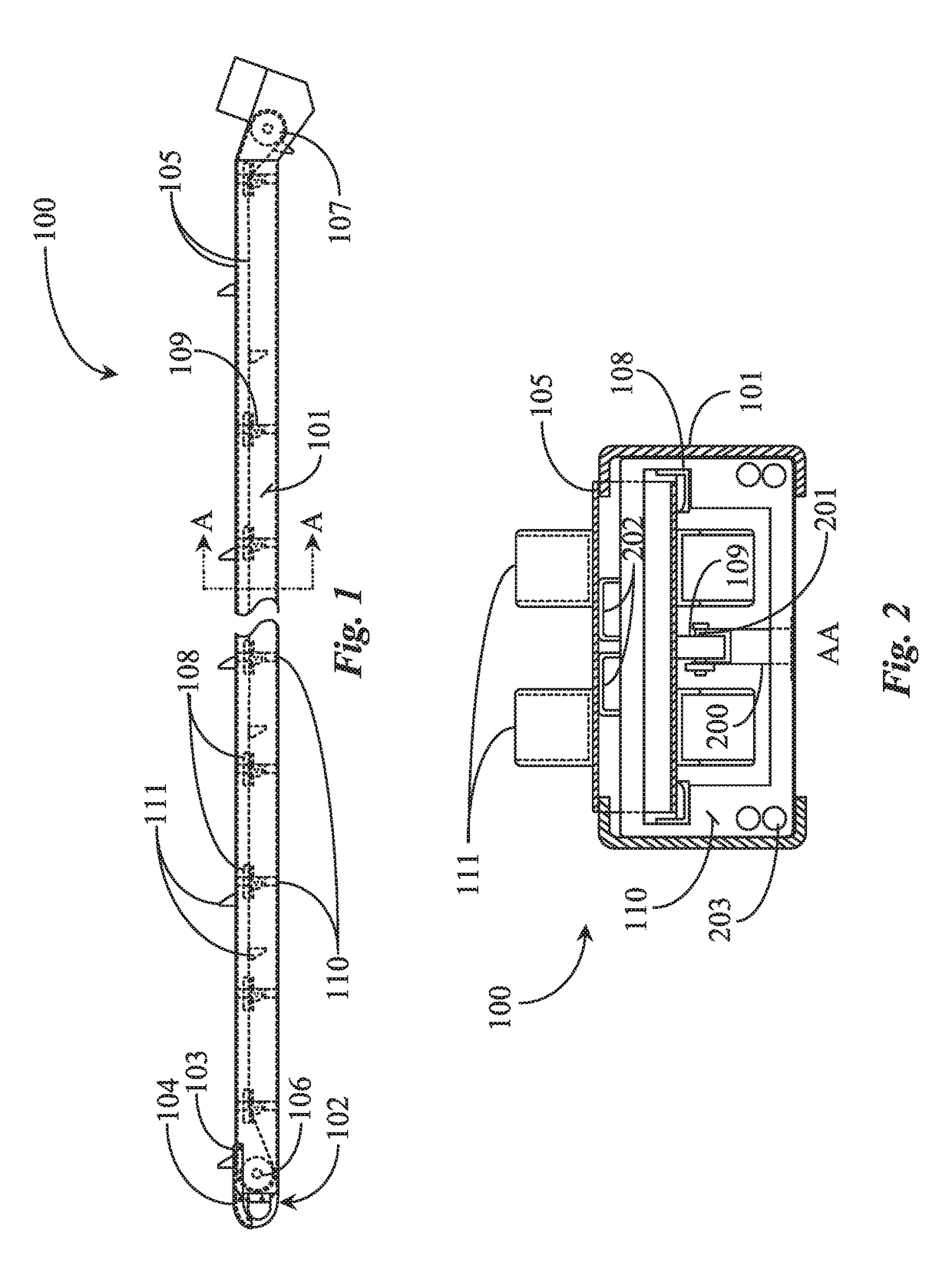
[0050]FIG. 1 is a side elevation view of conveyor apparatus 100 according to an embodiment of the present invention. Conveyor apparatus 100 is adapted as a hydraulically powered conveyor belt 105 supported at both ends by roller assemblies 106 and 107 and by a hydraulically powered boom assembly constructed of substantially parallel side rails 101 held together by a plurality of structural cross frame members 110 d...


PUM


Abstract

A telescopic material conveyer apparatus has a main boom assembly reinforced by a steel saddle frame connected to a turn table and a lift mechanism, an extension boom assembly adapted by two or more roller assemblies and connecting hardware to travel mechanically within the main boom assembly and to extend therefrom, one or more connected drive motors, a conveyer belt supported by frame architecture and a pulley and drive chain system, at least one hydraulic motor having operative connection to the turntable, lift mechanism and to a belt drive drum, at least one hydraulic valve connected inline in the hydraulic line controlling the belt drive motor, the valve electronically operable via input received from a load sensor integrated within or to the lift mechanism, a programmable load threshold determining open and close operation states of the valve and directing run and stop state operations of the conveyer belt.

Description

CROSS-REFERENCE TO RELATED DOCUMENTS[0001]The present invention is a continuation in part CIP of U.S. patent application Ser. No. 15 / 370,819, entitled “CONVEYER APPARATUS” filed on Dec. 6, 2016, which is a divisional of U.S. patent application Ser. No. 14 / 985,227 filed on Dec. 30, 2015. The disclosures of the above patent applications are included herein in their entirety at least by reference.BACKGROUND OF THE INVENTION1. Field of the Invention[0002]The present invention is in the field of construction and pertains particularly to methods and apparatus for safely conveying materials to and from a rooftop.2. Discussion of the State of the Art[0003]In the field of construction equipment, more particularly in the roofing industry, roofing materials have traditionally been carried or lifted onto a roof top manually by the workers without any mechanical assistance other than a ladder. This caused injuries to workers.[0004]Another problem in the art is that customers want to be able to t...

Claims


Application Information

Patent Timeline
Patent Type & Authority Applications(United States)
IPC IPC(8): B65G15/62B65G21/00B65G15/44B65G21/02B65G15/64
CPCB65G15/44B65G15/64B65G15/62B65G2207/10B65G2207/48B65G21/02B65G21/00B60P1/38B65G15/26B65G21/14B65G41/005
Inventor PORTER, ROBIN D.PORTER, CHAD T.
Owner CLEASBY LLC
Why Eureka
Try Eureka