Hand held appliance

a hand-held and hand-held technology, applied in the field of hand-held appliances, can solve problems such as motors being susceptible to damag

Inactive Publication Date: 2017-11-07
DYSON TECH LTD
View PDF244 Cites 26 Cited by
  • Summary
  • Abstract
  • Description
  • Claims
  • Application Information

AI Technical Summary

Benefits of technology

[0029]Forming the body and the wall of the handle as a single unit has a number of advantages. Firstly the access to at least some of the components of the appliance is made more difficult. In convention hairdryers, a clam shell construction is used and the two parts are usually screwed together. A user can relatively easily remove the screws and access the heater and fan unit. In the present invention, as there are no joins or screws that can be removed, it is made more difficult for a user to take the product apart. Secondly, the product is visually cleaner. There are no join lines running along the length of the body and no recesses or extensions in the body that would be required in order to connect the two parts.
[0068]Having the primary fluid inlet disposed one more than one surface of the appliance is advantageous. In conventional hairdryers, the primary fluid inlet is generally located on the back end of the hairdryer and in an attempt to prevent blockage, the end is often convex. If the back end of the hairdryer is placed down on a hard surface, it will roll onto a side.
[0069]However, on a soft surface such as bedding or a long pile carpet, the inlet can still be at least partially covered or blocked. This can lead to overheating of the motor. By having the inlet on more than one surface, there is less chance of any blockage being sufficient to cause damage to the motor.
[0085]The provision of a double layered wall reduces the transmission of vibration and noise from within the handle. It isolates internal components of the handle from the outer wall.
[0087]Preferably, the insulating layer mitigates one or more of noise, vibration and heat produced by the appliance. It is preferred that the insulating material is a foam or a felt.

Problems solved by technology

The motor is susceptible to damage from foreign objects such as dirt or hair so conventionally a filter is provided at the fluid intake end of the blower.

Method used


Image

  • Hand held appliance
  • Hand held appliance
  • Hand held appliance

Examples


Embodiment Construction

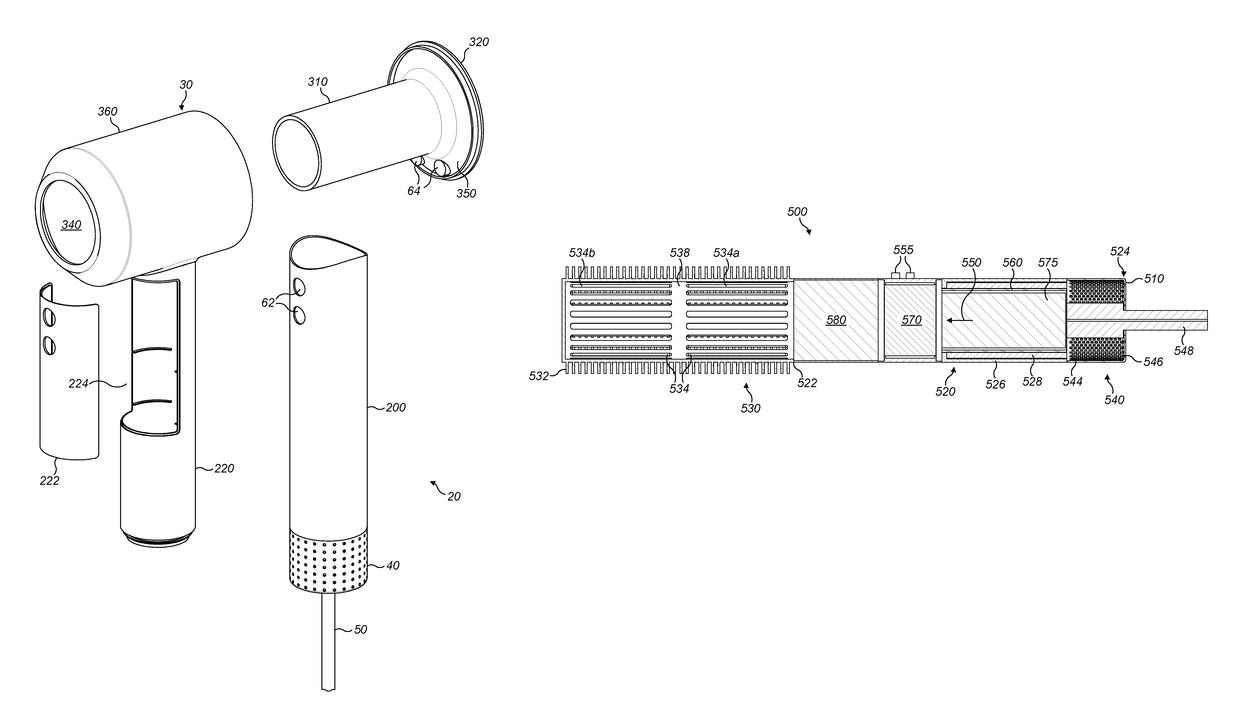
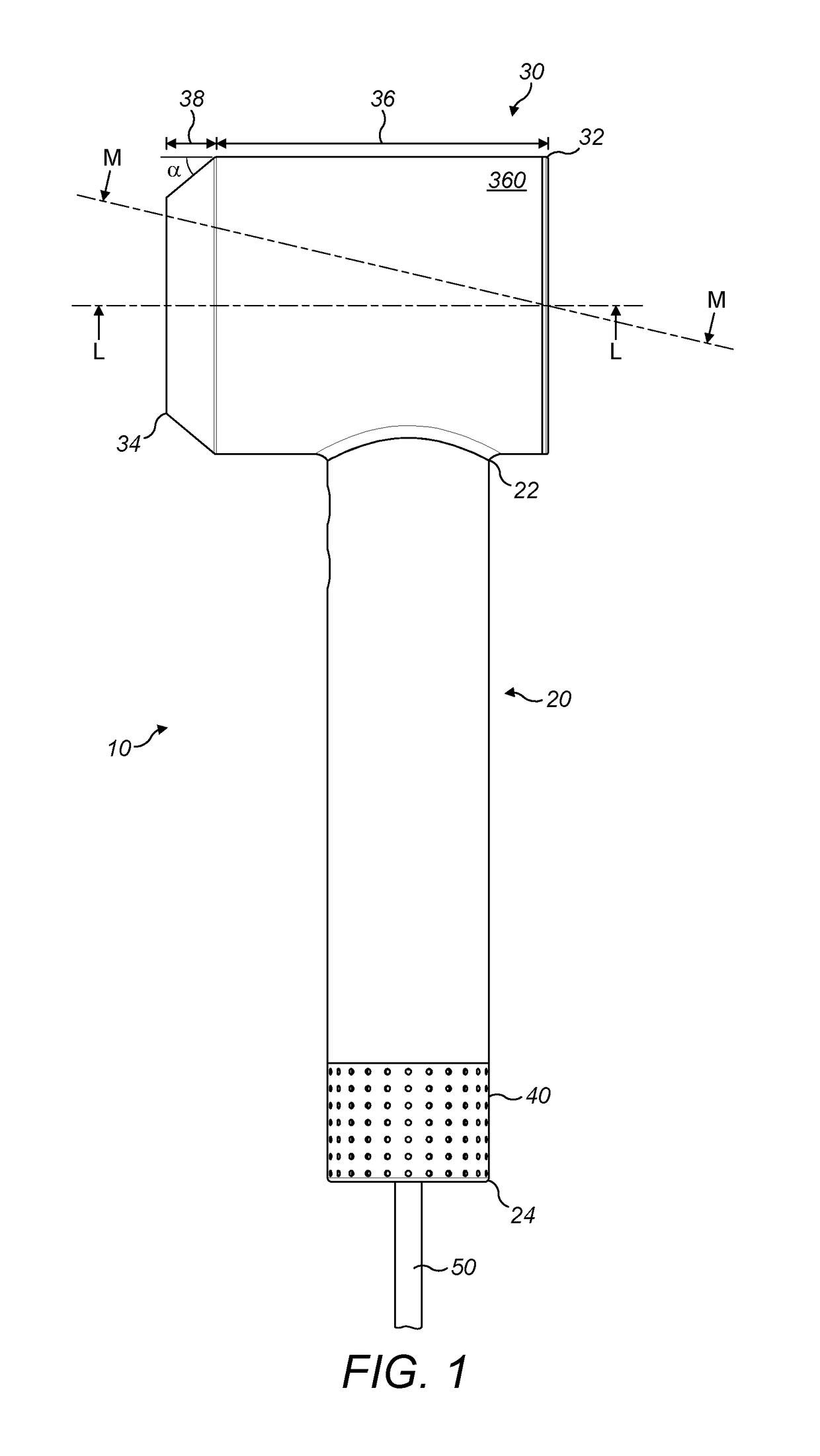
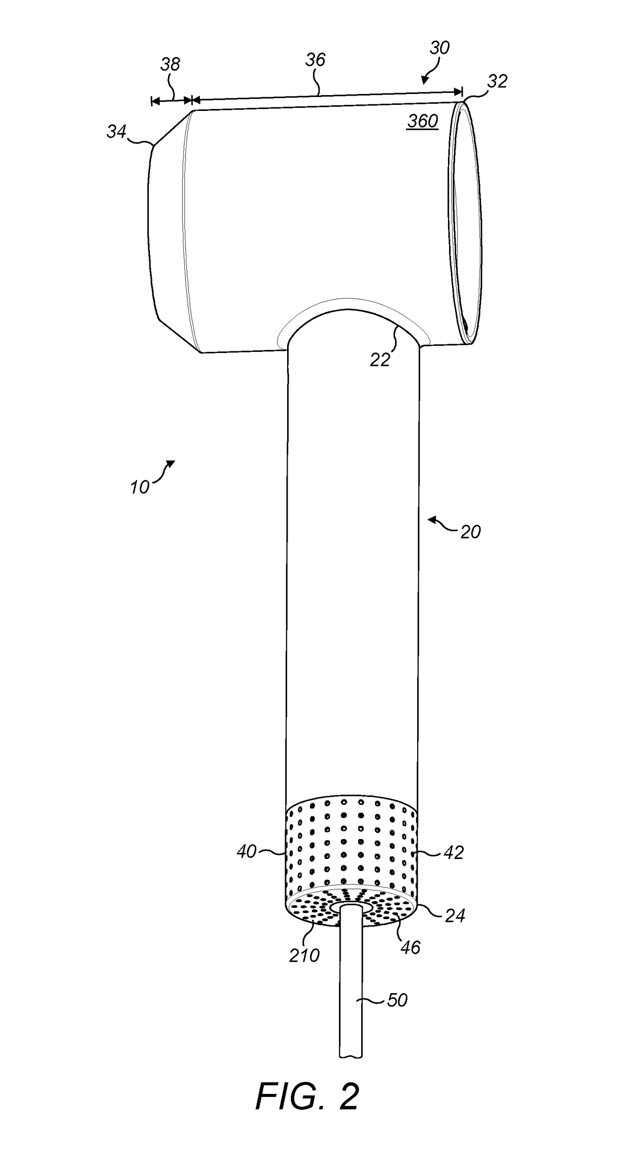
[0168]FIGS. 1 and 2 show a hairdryer 10 with a handle 20 and a body 30. The handle has a first end 22 which is connected to the body 30 and a second end 24 distal from the body 30 and which includes a primary inlet 40. Power is supplied to the hairdryer 10 via a cable 50.

[0169]The body 30 has a first end 32 and a second end 34 and can be considered to have two parts. A first part 36 which extends from the first end 32 which is tubular and of a generally consistent diameter and a second part 38 which extends from the second end 34 to join the first part 36. The second part 38 is cone shaped and varies in diameter along its length from the diameter of the first part 36 of the body 30 to a smaller diameter at the second end 34 of the body. In this example, the second part 38 has a constant gradient and the angle α subtended from the outer wall 360 of the first part 36 of the body 30 is around 40°.

[0170]Referring now to FIGS. 2, 3, 4a and 4b in particular the handle 20 has an outer wall...


PUM


Abstract

A hair care appliance including, a body, a heater, a PCB and a primary fluid flow path extending from a primary fluid inlet into the appliance to a primary fluid outlet out of the body wherein the PCB and heater are in fluid communication with the primary fluid flow path and the PCB is upstream of the heater. A fan unit may be provided and the fan unit is upstream of the heater and may be upstream or downstream of the PCB. A thermal barrier may be provided between the PCB and the heater. The thermal barrier may be in thermal communication with the PCB and functions as a heat sink for the PCB.

Description

REFERENCE TO RELATED APPLICATIONS[0001]This application is a national stage application under 35 USC 371 of International Application No. PCT / GB2014 / 051834, filed Jun. 13, 2014, which claims the priority of United Kingdom Application No. 1312073.8, filed Jul. 5, 2013, the entire contents of which are incorporated herein by reference.FIELD OF THE INVENTION[0002]This invention relates to a hand held appliance, in particular a hair care appliance such as a hairdryer or a hot styling brush.BACKGROUND OF THE INVENTION[0003]Blowers and in particular hot air blowers are used for a variety of applications such as drying substances such as paint or hair and cleaning or stripping surface layers. In addition, hot air blowers such as hot styling brushes are used to style hair from a wet or dry condition.[0004]Generally, a motor and fan are provided which draw fluid into a body; the fluid may be heated prior to exiting the body. The motor is susceptible to damage from foreign objects such as dir...

Claims


Application Information

Patent Timeline
Patent Type & Authority Patents(United States)
IPC IPC(8): A45D20/10A45D2/00A45D20/50A45D20/48A45D20/12
CPCA45D20/10A45D2/00A45D20/50A45D20/48A45D20/122A45D20/12A45D20/52
Inventor MOLONEY, PATRICK JOSEPH WILLIAMGOSNAY, ANTHONY THOMASHARROD, NICHOLAS STUARTTWEEDIE, ROBERT LAWRENCEWILKINSON, CHRISTOPHER DANIELCOURTNEY, STEPHEN BENJAMIN
Owner DYSON TECH LTD
Why Eureka
Try Eureka