
Device and method for automatically twisting metal wires, in particular for connecting adjacent, preferably mutually intersecting structure elements

a technology of automatic twisting and metal wires, which is applied in the direction of building construction, building material handling, construction, etc., can solve the problems of exhausting activity for the person performing the activity and also very time-consuming, and achieve the effect of shortening the formed loop

Inactive Publication Date: 2017-11-07
WOBBEN PROPERTIES GMBH
View PDF36 Cites 0 Cited by
  • Summary
  • Abstract
  • Description
  • Claims
  • Application Information

AI Technical Summary

Benefits of technology

[0010]One or more embodiments of the invention however also goes still further insofar as it provides an apparatus which also makes it possible for the wire to be passed around the twisting region of two or more adjacent, preferably mutually crossing structural elements, in an automated procedure, thereby significantly speeding up the entire working procedure. The interaction of automatedly passing the wire around the twisting region and the automated twisting operation is based on the following central notions: the wire is moved along an arcuate wire guide to ensure a high level of reproduction accuracy in terms of forming the loop by the wire. To be able to arrange the arcuate wire guide which is provided on the apparatus in such a way as to surround the twisting region, there is an opening in the arcuate wire guide. Even in the case of twisting regions which involve difficulties of access, as are to be found for example in relation to reinforcing cages for prestressed concrete components, that makes it possible to easily move the apparatus to the twisting region, engage around the twisting region with an opened arcuate wire guide, and to enclose the twisting region by closing the opening. The mode of operation is for example similar to a tongs arrangement. In addition one or more embodiments of the invention is distinguished in that the wire is pulled along the arcuate wire guide by the pulling slider. The configuration according to one embodiment of the invention of pulling guidance for the wire along the arcuate wire guide can be used for soft wires which permit better twisting than wires of hard material. The apparatus according to one embodiment of the invention, by opening and closing of the arcuate wire guide, makes it possible to place the arcuate wire guide around the twisting region of two structural elements, and the moveable pulling slider then makes it possible to pass the wire which has been fed on one side of the arcuate wire guide, with the arcuate wire guide closed, around the twisting region, along the arcuate wire guide. Finally the twisting unit can then engage the wire which has been passed around the twisting region by the pulling slider on both sides of the twisting region or on both sides of the arcuate wire guide and perform the twisting operation, for example by means of the rotational drive.
[0012]An advantageous development of one embodiment of the invention provides that the twisting unit has a first wire guide passage hole and a second wire guide passage hole and wherein the wire feed means is adapted to pass the fed wire through the first wire guide passage hole. In that way, it is already possible, when feeding the wire in the direction of the arcuate wire guide, to prepare for later engagement of the wire by the twisting unit. The wire can already be engaged by the twisting unit, by being passed through the wire guide passage hole.
[0014]In a preferred embodiment the apparatus according to one embodiment of the invention has a clamping device which is preferably arranged on the first or the second side of the arcuate wire guide and which is adapted to hold fast the wire passed through the first wire guide passage hole or is adapted to hold fast the wire passed through the second wire guide passage hole. In particular the clamping device is adapted to move the wire after formation of the loop beyond the twisting region of the two structural elements so that twisting by the twisting unit can be further prepared.
[0019]In a further preferred embodiment the twisting unit has two coaxially arranged gears through which the first and second wire guide passage holes respectively completely extend and wherein the two gears are drivable both in opposite directions and also in the same direction. Preferably the two coaxially arranged gears are arranged in directly mutually adjacent relationship. Driving the two gears in opposite directions preferably causes clamping of the wire passed through the first and second wire guide passage holes. That makes it possible for the wire to be engaged by the twisting unit. The drive is preferably implemented by means of a respective servo motor.
[0021]Further preferably the apparatus according to one embodiment of the invention has a cutting body which is arranged to sever the wire within the apparatus and is adapted to sever the wire on the first side of the arcuate wire guide and / or on the second side of the arcuate wire guide. That additionally permits severing of the wire prior to twisting without having to carry separate tools with oneself. The apparatus according to one embodiment of the invention thus permits, in a single continuous working procedure, the feed of wire, passing the wire around an assembly of structural elements that is to be twisted, cutting the wire portion provided for the twisting operation from a wire portion at the feed side, and finally twisting the wire.
[0047]a wire feed means for feeding wire, preferably endless wire, into the apparatus, an arcuate wire guide which has a selectively openable and closable opening and which is adapted to guide the fed wire in the closed position along the arcuate wire guide from a first side of the arcuate wire guide to a second side of the arcuate wire guide, that is in opposite relationship with respect to the opening, a pulling slider adapted to engage the fed wire on the first side of the arcuate wire guide and to pull it towards the second side of the arcuate wire guide, and a twisting unit adapted to engage the fed wire on both sides of the arcuate wire guide and to twist it by means of a rotational movement. In this case the reinforcing cage as first and second structural elements has a plurality of first and second prestressing cables arranged in mutually crossing relationship. The prestressing cables can optionally be braided together, which facilitates positioning of the prestressing cables prior to twisting of the wire and enhances the stability of the cage.

Problems solved by technology

As the wires to be used for the twisting operation must also have a certain stability, that activity is exhausting for the persons performing that activity and is also very time-consuming.

Method used


Image

  • Device and method for automatically twisting metal wires, in particular for connecting adjacent, preferably mutually intersecting structure elements
  • Device and method for automatically twisting metal wires, in particular for connecting adjacent, preferably mutually intersecting structure elements
  • Device and method for automatically twisting metal wires, in particular for connecting adjacent, preferably mutually intersecting structure elements

Examples


Embodiment Construction

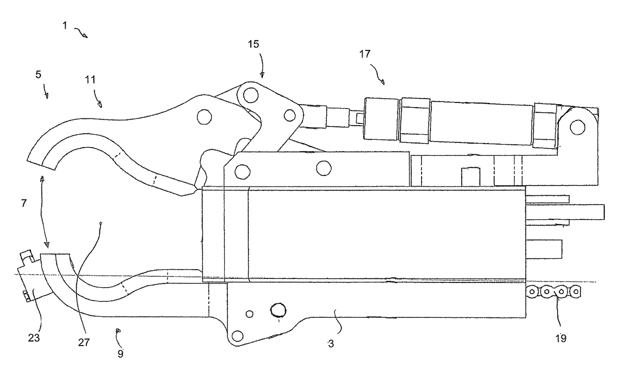
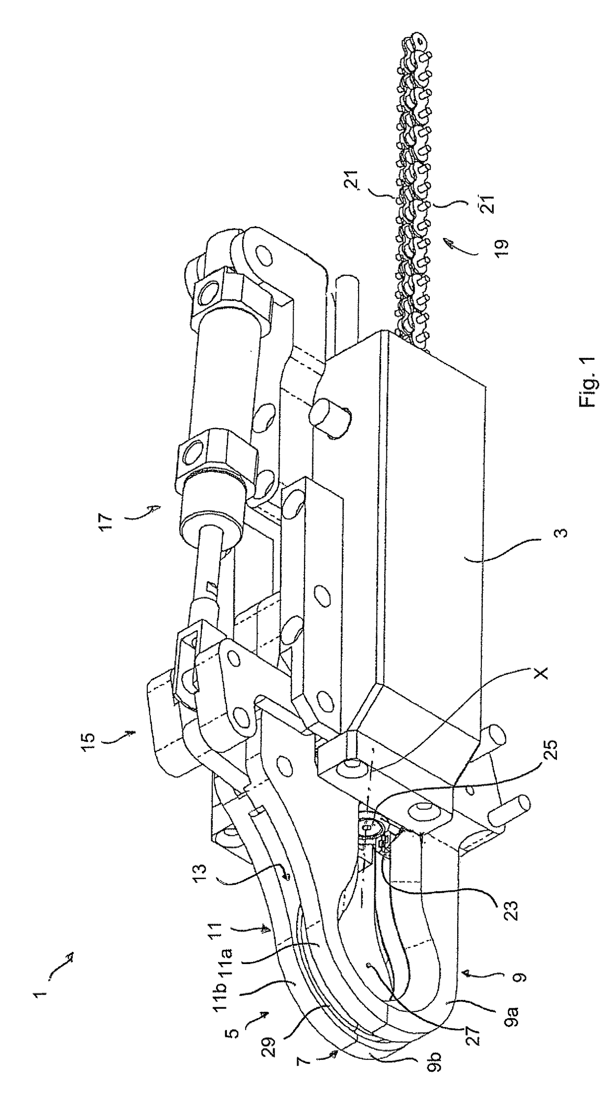
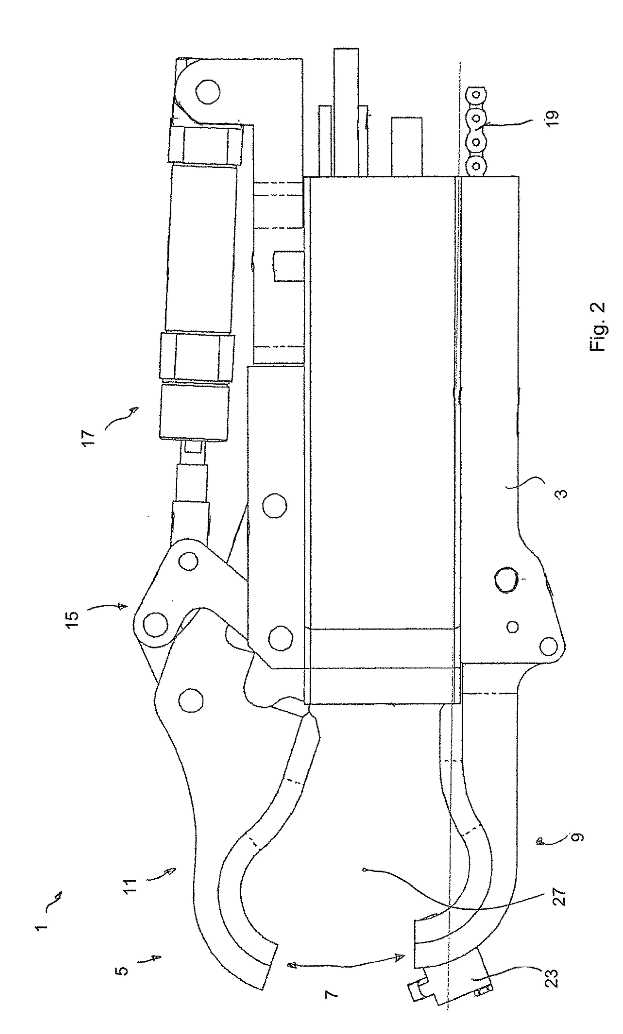
[0054]FIG. 1 shows an apparatus 1 for automatically twisting metal wires. The apparatus 1 has a main body 3. Arranged on the main body 3 at a proximal end of the apparatus 1 is an arcuate wire guide 5. The arcuate wire guide 5 has a closable and openable opening 7 arranged substantially centrally between a first side 9 of the arcuate wire guide 5 and a second side 11 of the arcuate wire guide 5.

[0055]In the illustrated embodiment the first side 9 of the arcuate wire guide is arranged fixedly relative to the main body 3 while the second side 11 of the arcuate wire guide 5 can be deflected by means of a lever mechanism 15 in such a way that the opening 7 is moved from the closed position shown in FIG. 1 into an open position (FIG. 2). In the illustrated embodiment the lever mechanism 15 is driven by means of a pneumatic cylinder 17.

[0056]The arcuate wire guide 5 is of a substantially tongs-like configuration and in the interior of the two sides 9, 11 of the arcuate wire guide has a re...


PUM

PropertyMeasurementUnit
sizeaaaaaaaaaa
lattice-like structureaaaaaaaaaa
stabilityaaaaaaaaaa

Abstract

The invention concerns an apparatus, a method and a use of the apparatus for automatically twisting metal wires. The invention concerns in particular such an apparatus for connecting adjacent, preferably mutually crossing structural elements, comprising a wire feed means for feeding wire, preferably endless wire, into the apparatus, an arcuate wire guide which has a selectively openable and closable opening and which is adapted to guide the fed wire in the closed position along the arcuate wire guide from a first side of the arcuate wire guide to a second side of the arcuate wire guide, that is in opposite relationship with respect to the opening, a pulling slider adapted to engage the fed wire on the first side of the arcuate wire guide and to pull it towards the second side of the arcuate wire guide, and a twisting unit adapted to engage the fed wire on both sides of the arcuate wire guide and to twist it by means of a rotational movement.

Description

BACKGROUND[0001]Technical Field[0002]The present invention concerns an apparatus for automatically twisting metal wires, in particular for connecting adjacent, preferably mutually crossing structural elements. The term structural element is used in the context of this invention to denote an elongate body of a round or polygonal, for example quadrangular cross-section. Examples of such structural elements are for example tubes, bars or carriers, as are used in many respects in all fields of industry. Stranded wire bundles, so-called stranded wire cables, or prestressing cables are also viewed as being embraced by the term structural element, being used inter alia for the production of reinforcing cages for prestressed concrete components.[0003]Description of the Related Art[0004]A typical area of use for apparatuses of the kind set forth in the opening part of this specification is the production of such reinforcing cages, for example for prestressed concrete elements. Reinforcing ca...

Claims


Application Information

Patent Timeline
Patent Type & Authority Patents(United States)
IPC IPC(8): B21F15/04E04G21/12
CPCE04G21/123B21F15/04
Inventor HORN, GUNTHER
Owner WOBBEN PROPERTIES GMBH
Learn More