Rolling tarp enclosure system

a technology of enclosure system and tarp cover, which is applied in the direction of engine seals, roofs, vehicle sealing arrangements, etc., can solve the problems of shortening the useful life of wheels, difficult to fully tension the tarp cover to the upper end, and affecting the use of the tarp cover, so as to achieve convenient and safe use and adjustment, and the effect of being more durabl

Active Publication Date: 2017-11-07
DEMONTE WALTER PETER +2
View PDF12 Cites 6 Cited by
  • Summary
  • Abstract
  • Description
  • Claims
  • Application Information

AI Technical Summary

Benefits of technology

[0027]The present invention has been created with the intention of meeting the discussed need. It is an object of the present invention to provide a rolling type tarpaulin cover syste

Problems solved by technology

While such previously disclosed tensioning mechanisms function appropriately for tensioning the tarp cover, they have limitations associated therewith.
For example, while the applicant's prior locking tensioning mechanism in U.S. Pat. Nos. 7,854,465 and 8,047,600 functions appropriately to tension the tarp cover, it only engages the rearmost carriage at the bottom portion of the tarp cover which makes it somewhat challenging to tension the tarp cover fully to the upper end thereof.
This is acceptable, but some additional means should be provided to prevent any undue or unbalanced forces from being applied to the wheels of the rearmost rolling carriage because undue or unbalanced forces would significantly shorten the useful life of the wheels.
Conversely, the applicant's rolling tarp system, commercially sold under the trademark Quick Draw™, has rolling carriages with wheels that roll along the top of the rail, and hence cannot use the Loc-N-Load Mechanism because it would interfere with movements of the rearmost rolling carriage.
However, it also has some limitations associated therewith.
This creates some difficulties during initial installation of locking and tensioning mechanism, as well as throughout the life of the tarp cover system as it may become necessary for a driver to remove and re-install, or reposition the locking and tensioning mechanism on location wherever the trailer may be disposed at any given time.
This complicates the work required by persons installing and operating the system, and may lead to safety issues if done too hastily or otherwise improperly.
Such flatbed trailers may also be equipped with rolling type tarp cover systems, but such systems have conventionally required a second

Method used


Image

  • Rolling tarp enclosure system
  • Rolling tarp enclosure system
  • Rolling tarp enclosure system

Examples


Embodiment Construction

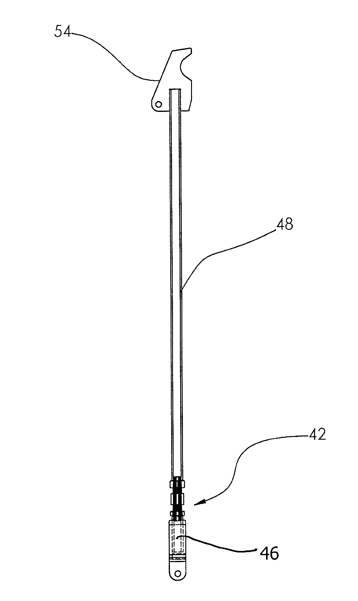
[0069]A number of selected illustrative and exemplary embodiments of the invention will now be described in some detail, with reference to the drawings. It should be understood that only structures considered necessary for clarifying the present invention are described herein. Other conventional structures, and those of ancillary and auxiliary components of the system, are presumed to be known and understood by those skilled in the art. These illustrative embodiments include locking and tensioning devices for tarp enclosure systems being mounted on flatbed trailers, other vehicles or the like, and various components of such systems.

Movable Rail for Systems Used on Drop Deck Trailers

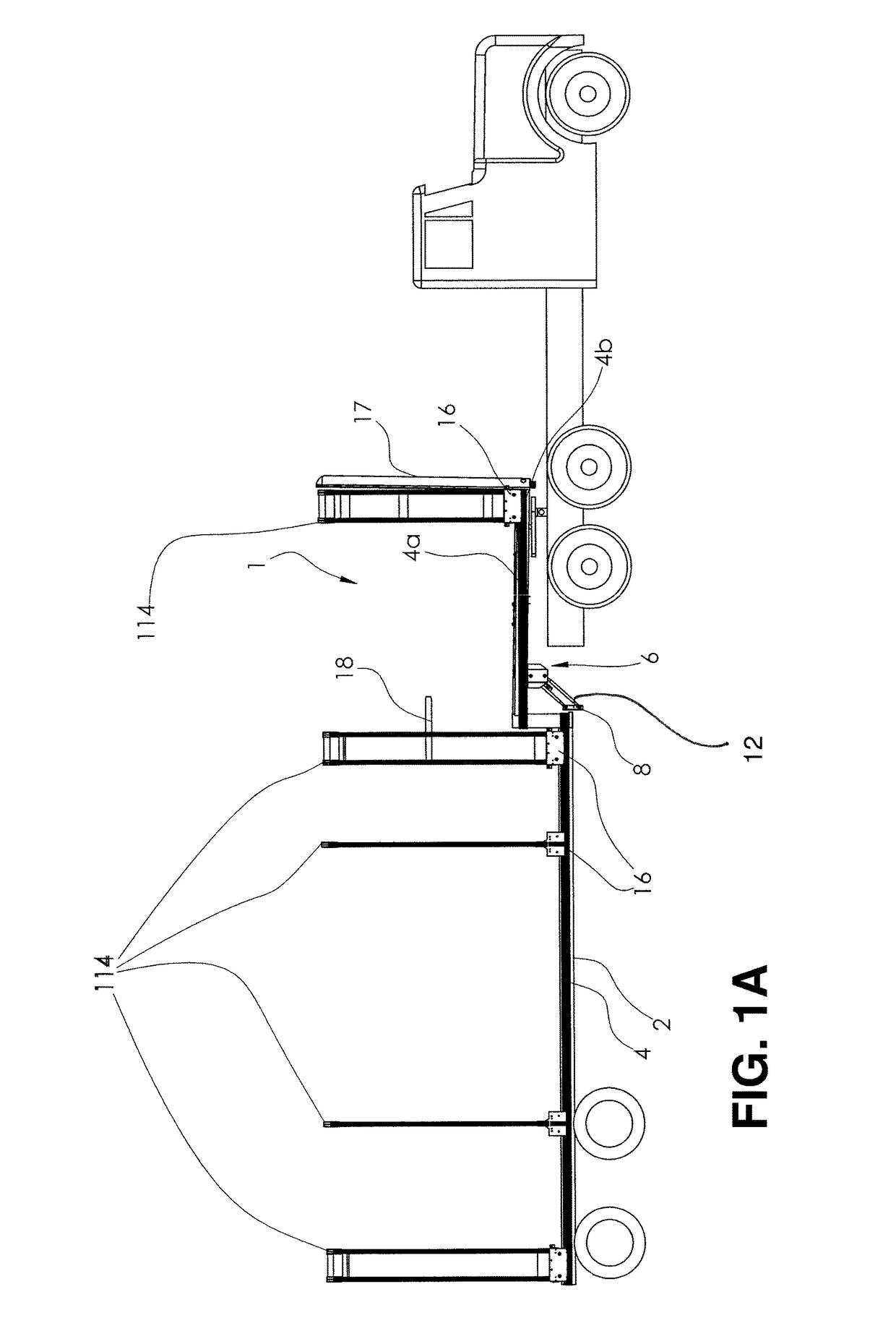
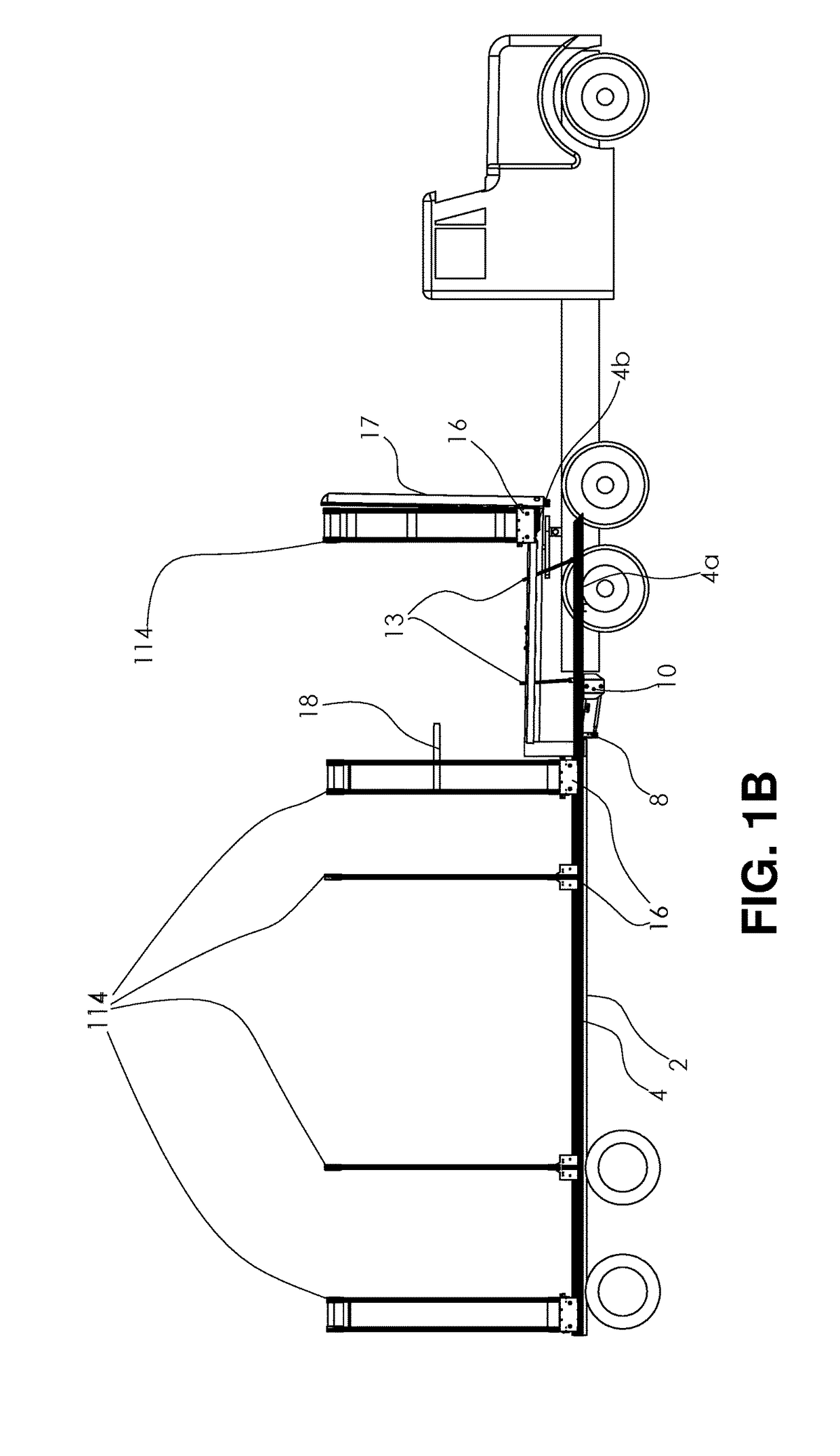
[0070]Referring now to FIGS. 1A-1E of the drawings, there are shown side elevational views of a rolling type tarp cover system 1 disposed in various positions on a drop deck type flatbed trailer 2 according to an exemplary embodiment of the present invention. In these figures a tarp cover, which is an out...


PUM


Abstract

A tensioning mechanism for a movable, tarp enclosure system including first, second, and third arms, and first and second support brackets which are all connected together in a substantially triangular, adjustable configuration in which the first arm is rotatable relative to support brackets and when the first arm is rotated, the first bracket moves linearly along the first arm toward and away from the second bracket. The second arm has one end thereof pivotally connected to the first bracket such that the first end of the second arm moves together with the first bracket, the third arm has an engagement member provided on one end thereof which is configured to operatively engage a vertically intermediate portion of an end one of the bows, and the third arm has a length adjusting mechanism for adjusting a length thereof.

Description

CROSS REFERENCE TO RELATED APPLICATIONS[0001]The present application is a continuation of, and claims priority under 35 USC 120 based on U.S. patent application Ser. No. 15 / 370,135, filed 6 Dec. 2016. The entire disclosure this prior application is incorporated herein by reference.BACKGROUND OF THE INVENTION[0002]1. Field of the Invention[0003]This invention relates to an improved rolling tarp enclosure system. More particularly, the invention relates to several improvements for a retractable tarp enclosure system which may be used for covering substantially any area or object, including swimming pools, beds of trucks, flatbed trailers and the like. More particularly, the present invention relates to such a rolling tarp enclosure system with improvements to a rail and rolling carriage arrangement thereof, to tensioning arrangements thereof, to corner portions of end sections thereof, and to other aspects of the rolling tarp enclosure system.[0004]2. Discussion of Background Art[0005...

Claims


Application Information

Patent Timeline
IPC IPC(8): B60J7/06B60J7/02B60J7/185B60J10/90
CPCB60J7/065B60J7/022B60J7/1855B60J10/90B60J7/185B60J7/104
Inventor DEMONTE, WALTER PETERDEMONTE, TIMOTHY PAULLEBLANC, SHERI LYN
Owner DEMONTE WALTER PETER
Why Eureka
Try Eureka