Current detection and averaging circuit for switching power supplies with a half-bridge switch circuit topology

Active Publication Date: 2017-11-07
MONOLITHIC POWER SYST
View PDF4 Cites 6 Cited by
  • Summary
  • Abstract
  • Description
  • Claims
  • Application Information

AI Technical Summary

Benefits of technology

The present invention relates to a power supply that includes a half-bridge circuit and an output inductor. The power supply also includes a current detection circuit that samples and holds in a capacitor a valley and a peak of the inductor current during the turn ON time of the low side switch. The current detection circuit also generates a sense inductor current that is representative of the inductor current during the turn OFF time of the low side switch. The technical effect of this invention is to provide a more efficient and accurate power supply that can regulate the output voltage and current, and reduce the size and cost of the power supply.

Problems solved by technology

However, for low duty cycle applications, the requirement for amplifier response time for high side current sensing is demanding and becoming unattainable as frequency becomes higher, when the high side switch turn ON time is shorter than the blanking time.

Method used


Image

  • Current detection and averaging circuit for switching power supplies with a half-bridge switch circuit topology
  • Current detection and averaging circuit for switching power supplies with a half-bridge switch circuit topology
  • Current detection and averaging circuit for switching power supplies with a half-bridge switch circuit topology

Examples


Embodiment Construction

[0015]In the present disclosure, numerous specific details are provided, such as examples of circuits, components, and methods, to provide a thorough understanding of embodiments of the invention. Persons of ordinary skill in the art will recognize, however, that the invention can be practiced without one or more of the specific details. In other instances, well-known details are not shown or described to avoid obscuring aspects of the invention.

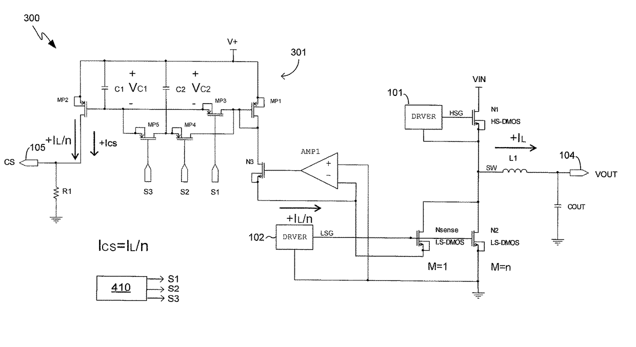
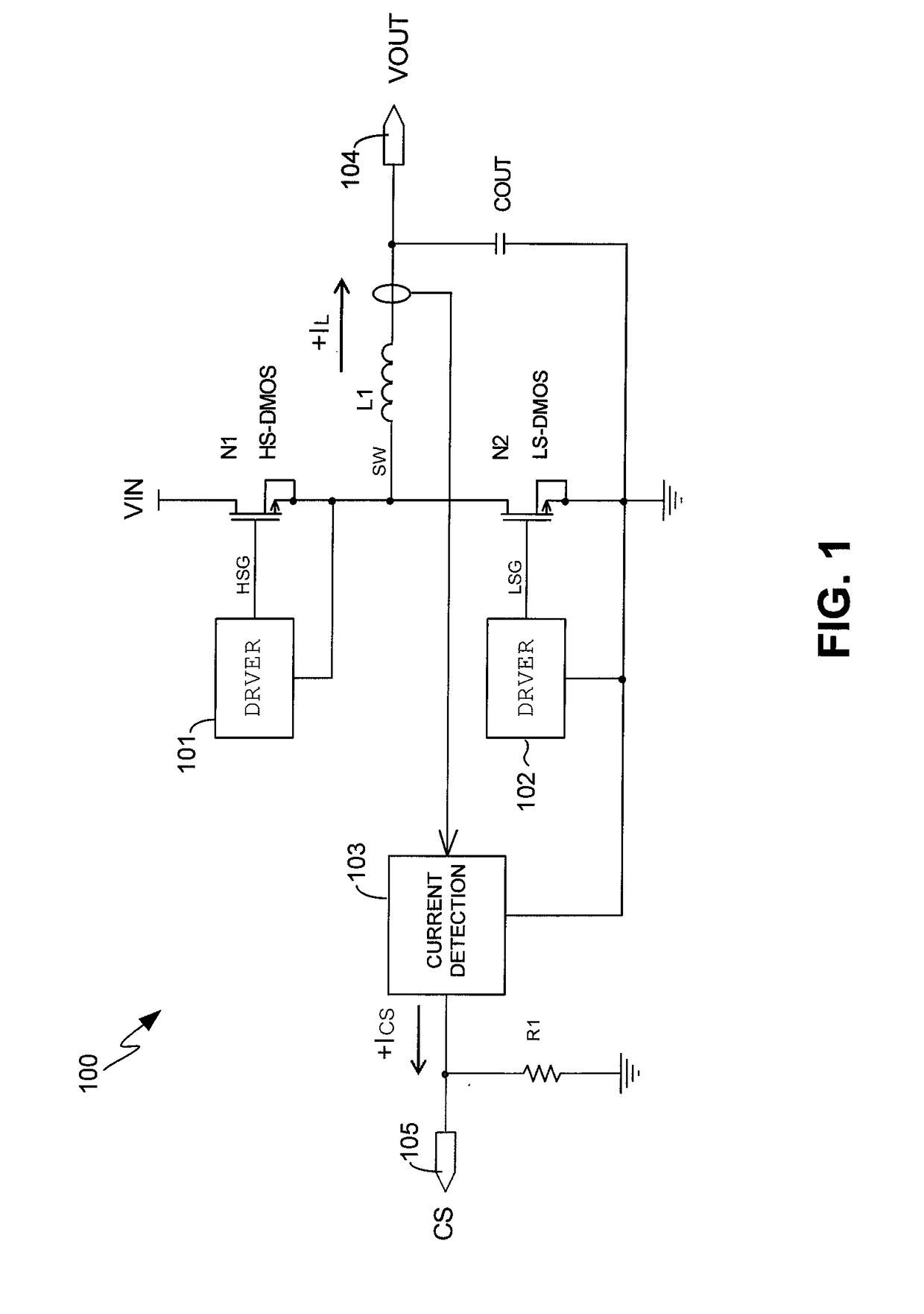
[0016]FIG. 1 shows a schematic diagram of a half-bridge circuit 100 that may take advantage of embodiments of the present invention. The half-bridge circuit 100 may be part of a DC-DC buck converter, for example. As can be appreciated, embodiments of the present invention are also generally applicable to other power supply topologies.

[0017]In the example of FIG. 1, the half-bridge circuit 100 comprises a high side switch N1 and a low side switch N2. Each of the high side switch N1 and low side switch N2 may comprise an N-channel Double Diffu...


PUM


Abstract

A power supply includes a half-bridge circuit. The power supply further includes an output inductor connected to a switch node that is common to a high side switch and a low side switch of the half-bridge. During a turn ON time of the low side switch, a current detection circuit of the power supply samples and holds in a capacitor a valley of an inductor current flowing through the output inductor. Also during the turn ON time of the low side switch, the current detection circuit samples and holds in another capacitor a peak of the inductor current. During a turn OFF time of the low side switch, a sense inductor current that is representative of the inductor current is generated by combining the charges stored in the capacitors.

Description

BACKGROUND OF THE INVENTION1. Field of the Invention[0001]The present invention relates generally to electrical circuits, and more particularly but not exclusively to inductor current sensing.2. Description of the Background Art[0002]A switching power supply includes a switch circuit, such as a half-bridge, that switches ON and OFF to maintain a regulated output voltage. A half-bridge circuit includes a high side switch that is connected to an input voltage and a low side switch that is connected to ground. The high side and low side switches have a common switch node. The high side switch is turned ON when the low side switch is turned OFF, thereby coupling the switch node to the input voltage. The high side switch is turned OFF when the low side switch is turned ON to connect the switch node to ground.[0003]The switch node is connected to an output inductor, which is connected to the load. Sensing the inductor current, i.e., the current through the output inductor, is critical for...

Claims


Application Information

Patent Timeline
IPC IPC(8): H02M3/158
CPCH02M3/158H02M3/07H02M3/156H02M3/1588Y02B70/10H02M1/0009
Inventor NGUYEN, JAMESYU, FRANCIS
Owner MONOLITHIC POWER SYST
Why Eureka
Try Eureka