Forceps manipulator and forceps system comprising forceps manipulator

a technology of forceps and manipulators, which is applied in the field of forceps manipulators and forceps system comprising forceps manipulators, can solve the problems of buckling or breaking, joint itself becoming longer, and affecting the work efficiency of the forceps, so as to achieve simple flexible bending mechanism, reduce size, and improve work efficiency.

Inactive Publication Date: 2017-11-14
TOKYO INST OF TECH
View PDF11 Cites 8 Cited by
  • Summary
  • Abstract
  • Description
  • Claims
  • Application Information

AI Technical Summary

Benefits of technology

[0003]In addition, for a forceps manipulator, as also shown in K. Xu, R. Goldman, J. Ding, P. Allen, D. Fowler, and N. Simaan, “System design of an insertable robotic effector platform for single port access (spa) surgery”, IEEE / RSJ International Conference on Intelligent Robots and Systems, pp. 5546-5552, 2009, for example, a flexible forceps manipulator is proposed that can bend with four degrees of freedom within the abdominal cavity of a human body. A bending portion of the forceps manipulator is divided into two segments. Each segment is bendable with two degrees of freedom. A bendable elastic body is formed by connecting a plurality of metal plates with a superelastic alloy tube running through the respective centers of the plurality of the metal plates. Further, its bendability is achieved by running through a driving tube or a wire made of superelastic alloy on peripheral portions of the metal plates. An upstream joint constituting one segment is driven by four superelastic alloy tubes, while a downstream joint constituting the other segment is driven by four superelastic alloy wires. The superelastic alloy wires for driving the downstream joint respectively run through inside the superelastic alloy tubes for driving the upstream joint. This gives advantageous effects of allowing for reducing an arrangement space for driving-force transmission components of the forceps manipulator, as well as simplifying kinematic calculations of the forceps manipulator.
[0004]Furthermore, for a forceps manipulator, as shown in Haraguchi, D., et al., “Development of Pneumatically-Driven Forceps Manipulator Using Push-Pull Mechanism Made of Superelastic Alloy Wire”, for example, a forceps manipulator for laparoscopic surgery is proposed that has a simple flexible bending mechanism suitable for reduction in size. A joint structure of the mechanism is made from only a machined spring molded in one piece. A superelastic alloy wire running through inside this joint structure is operated in a push-pull motion by a pneumatic cylinder, and this allows for bending motions with higher rigidity than an antagonistic driving that utilizes a conventional wire tension. This allows such a joint structure to bend in directions of two degrees of freedom.
[0005]Then, as shown in Daisuke Haraguchi, Kotaro Tadano, Kenji Kawashima, A Prototype of Pneumatically-Driven Forceps Manipulator with Force Sensing Capability Using a Simple Flexible Joint, 2011 IEEE / RSJ International Conference on Intelligent Robots and Systems, pp. 931-936, a simple theoretical model is proposed for estimating an external force in the forceps manipulator, which model approximates a flexible joint in the forceps manipulator by a rigid linkage mechanism with two degrees of freedom.SUMMARY OF THE INVENTIONProblems to be Solved
[0006]In the forceps manipulator as shown in Hagn, U., et al., DLR MiroSurge: a versatile system for research in endoscopic telesurgery, International Journal of Computer Assisted Radiology and Surgery, Vol. 5, p. 183-193 (2010), 10.1007 / s11548-009-0372-4, the arm located outside the human body is moved up and down as well as right and left, and may stand in the way of an assistant. In addition, if multiple forcipes are used, another problem may be caused such as the arms interfering with each other.
[0007]In addition, the components of the elastic body shown in K. Xu, R. Goldman, J. Ding, P. Allen, D. Fowler, and N. Simaan, “System design of an insertable robotic effector platform for single port access (spa) surgery”, IEEE / RSJ International Conference on Intelligent Robots and Systems, pp. 5546-5552, 2009 are wires and tubes only, then it is contemplated that rigidity of the joint against external forces (especially, torsional moments) may sometimes be insufficient. Further, a joint center requires a superelastic alloy tube as a backbone structure, then is subjected to buckling or breakage when being bent, receiving external forces, or the like. Furthermore, coupling disks are required to secure a range of bending motion, and this may cause the joint itself to become longer, to inhibit compact bending motions. As a solution, thickness of the disk may be decreased, but accordingly this makes a connecting area with the superelastic alloy to be decreased to cause the rigidity of the joint as described above to be decreased. If rigidity and strength of the joints are insufficient, not only the durability of the forceps manipulator, but also the operability of the forceps manipulator may be degraded even with a small external force such as one caused by contacting organs.
[0008]In the forceps manipulator as shown in Haraguchi, D., et al., “Development of Pneumatically-Driven Forceps Manipulator Using Push-Pull Mechanism Made of Superelastic Alloy Wire”, adopting a machined spring for the main structure of the joint has improved insufficient rigidity of the joint as a problem of the forceps manipulator shown in K. Xu, R. Goldman, J. Ding, P. Allen, D. Fowler, and N. Simaan, “System design of an insertable robotic effector platform for single port access (spa) surgery”, IEEE / RSJ International Conference on Intelligent Robots and Systems, pp. 5546-5552, 2009. However, because the joint has only two degrees of bending freedom, an additional four degrees of bending freedom need to be implemented by a retention manipulator outside the human body. The retention manipulator generally requires a larger moving space as compared to a tip portion, and this may cause a problem of interferences, while the retention manipulator is in operation, such as manipulators colliding with each other. Accordingly, a restriction may exist in the number of instruments used at the same time and in arranging those instruments, and additionally, in the forceps manipulator, when performing a roll operation of the tip, for example, all four cylinders need to be operated in a coordinated manner and this may sometimes cause degradation in controlling positions.

Problems solved by technology

In addition, if multiple forcipes are used, another problem may be caused such as the arms interfering with each other.
Further, a joint center requires a superelastic alloy tube as a backbone structure, then is subjected to buckling or breakage when being bent, receiving external forces, or the like.
Furthermore, coupling disks are required to secure a range of bending motion, and this may cause the joint itself to become longer, to inhibit compact bending motions.
If rigidity and strength of the joints are insufficient, not only the durability of the forceps manipulator, but also the operability of the forceps manipulator may be degraded even with a small external force such as one caused by contacting organs.
However, because the joint has only two degrees of bending freedom, an additional four degrees of bending freedom need to be implemented by a retention manipulator outside the human body.
The retention manipulator generally requires a larger moving space as compared to a tip portion, and this may cause a problem of interferences, while the retention manipulator is in operation, such as manipulators colliding with each other.
Accordingly, a restriction may exist in the number of instruments used at the same time and in arranging those instruments, and additionally, in the forceps manipulator, when performing a roll operation of the tip, for example, all four cylinders need to be operated in a coordinated manner and this may sometimes cause degradation in controlling positions.

Method used


Image

  • Forceps manipulator and forceps system comprising forceps manipulator
  • Forceps manipulator and forceps system comprising forceps manipulator
  • Forceps manipulator and forceps system comprising forceps manipulator

Examples


Embodiment Construction

[0029]Hereinafter, embodiments of the invention will be described. It should be noted that in the text of the present specification, an alphabetical character having a hat symbol will be referred to as “(alphabetical character) hat” and a character having an over-dot will be referred to as “(alphabetical character) over-dot.”

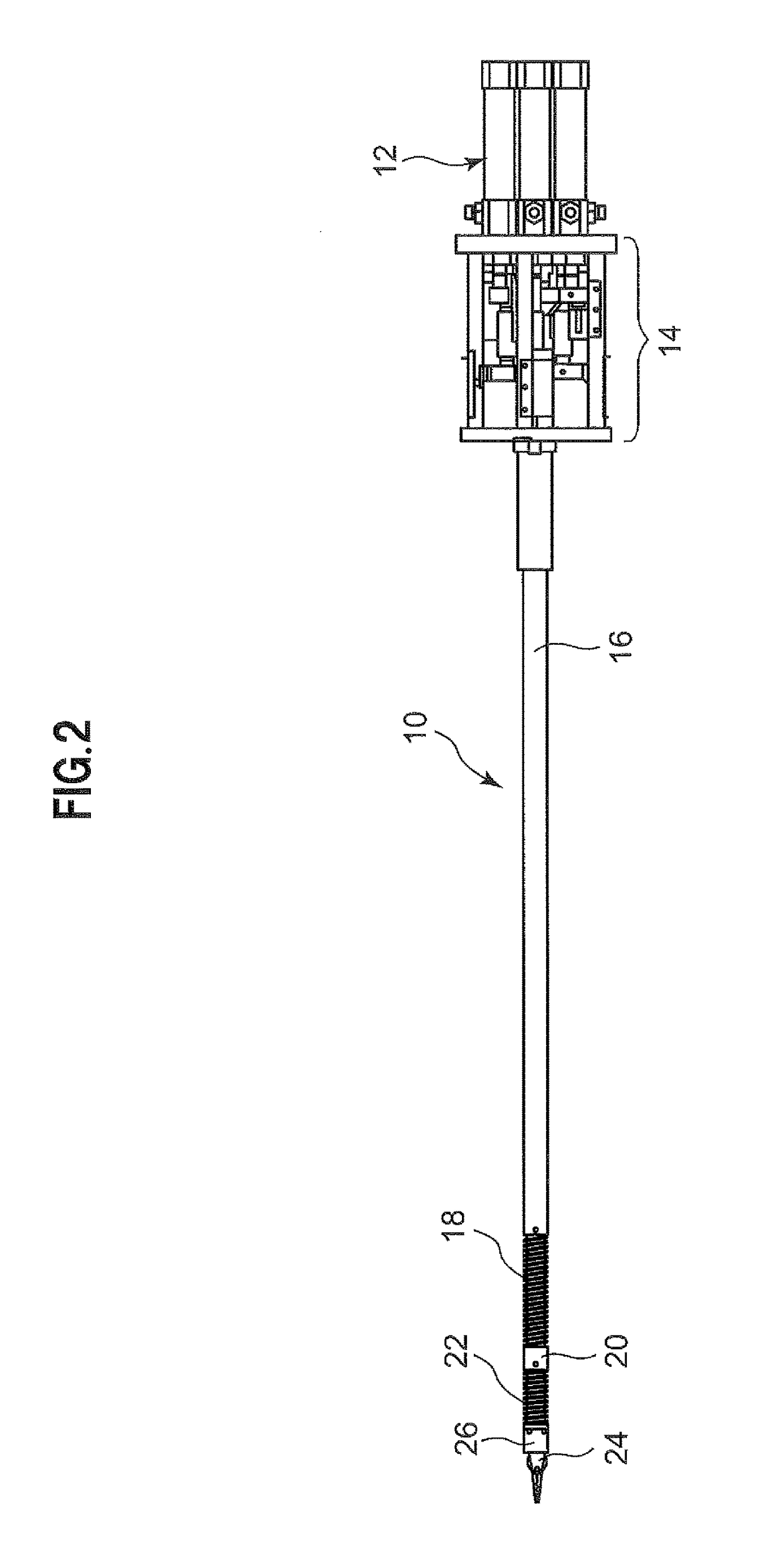
[0030]FIG. 2 shows an exterior view of a forceps manipulator used in an embodiment of a forceps system comprising the forceps manipulator according to the present invention.

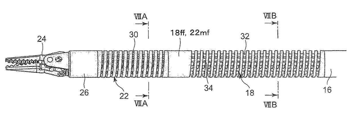
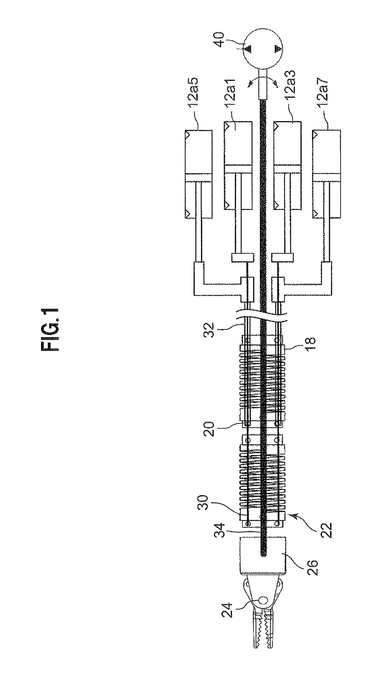
[0031]In FIG. 2, a forceps manipulator 10 is configured to include, as main components: a joint driving unit 12 composed of eight air cylinders 12a1 to 12a8; a connector unit 14 that connects respective piston rods of the joint driving unit 12 with a plurality of wires and tubes to be described later; a gripping unit 24 that is configured to include a forceps; a rotating joint unit 26 that is connected to a base end of the gripping unit 24; a second joint 22 that is connected via a ball beari...


PUM


Abstract

The present invention is intended to improve durability and operability of a forceps manipulator, as well as to facilitate roll motions of the forceps manipulator. In the forceps manipulator, a flexible shaft 34 is connected to a rotating joint unit 26 for transmitting a driving force from a vane motor 40 to the rotating joint unit 26 through throughholes 18a, 22a of machined springs 18b, 22b which respectively constitute flexible first and second joints 18, 22.

Description

TECHNICAL FIELD[0001]The present invention relates to a forceps manipulator and a forceps system comprising the forceps manipulator.BACKGROUND ART[0002]In a surgical robot system, a forceps system comprising a forceps manipulator is practically used. As shown in Hagn, U., et al., DLR MiroSurge: a versatile system for research in endoscopic telesurgery, International Journal of Computer Assisted Radiology and Surgery, Vol. 5, p. 183-193 (2010), 10.1007 / s11548-009-0372-4, for example, such a forceps manipulator has an arm with two degrees of freedom inside a human body (three degrees of freedom including a grip), and an arm with four degrees of freedom outside the human body. Such an arrangement is due to a restriction that implementing multiple degrees of freedom is difficult at a tip portion of a thin forceps provided in a forceps manipulator.[0003]In addition, for a forceps manipulator, as also shown in K. Xu, R. Goldman, J. Ding, P. Allen, D. Fowler, and N. Simaan, “System design ...

Claims


Application Information

Patent Timeline
Patent Type & Authority Patents(United States)
IPC IPC(8): A61B34/30A61B34/00A61B17/29A61B17/00
CPCA61B17/29A61B34/30A61B34/71A61B2034/306A61B2017/00544
Inventor TADANO, KOTAROKAWASHIMA, KENJIHARAGUCHI, DAISUKE
Owner TOKYO INST OF TECH
Why Eureka
Try Eureka