
Gripping device

a technology of a gripper and a gripper body, which is applied in the field of grippers, can solve the problems of difficult hand effective and safe gripping of objects, palm of hand inability to move about an axis, and inability of fingers to move laterally

Active Publication Date: 2017-11-14
5TH ELEMENT
View PDF11 Cites 27 Cited by
  • Summary
  • Abstract
  • Description
  • Claims
  • Application Information

AI Technical Summary

Benefits of technology

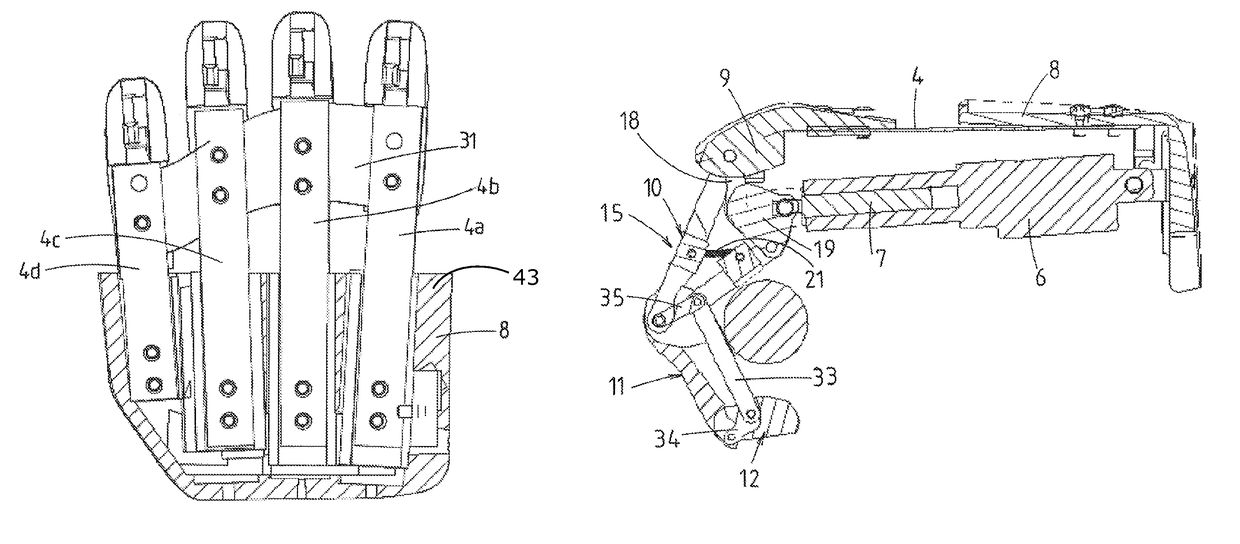
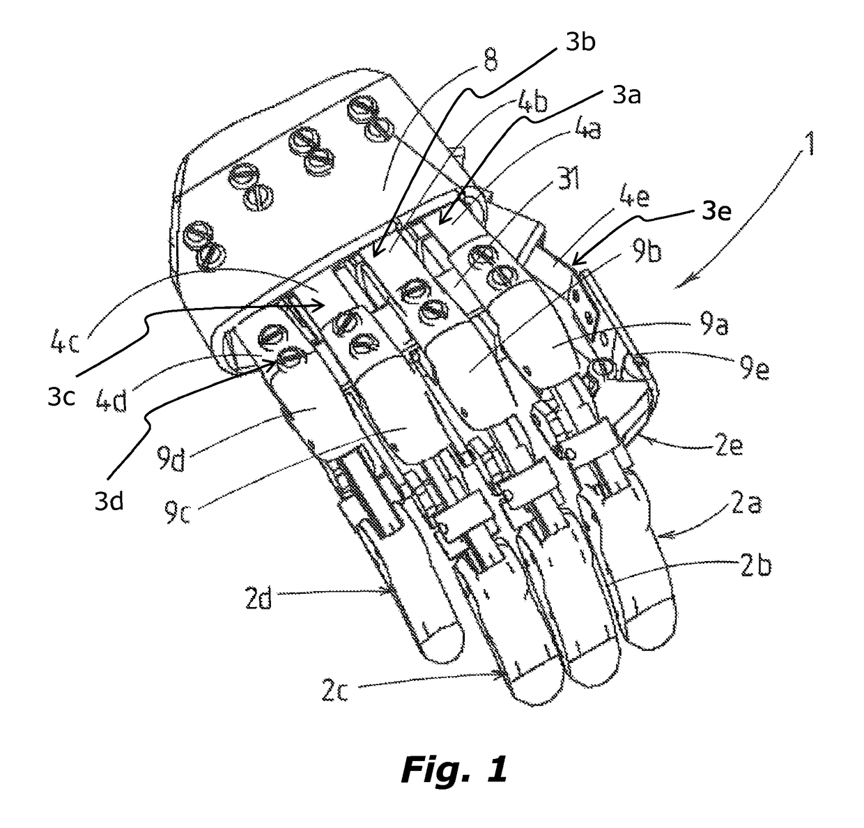
The invention is an automated hand that has metacarpal members that pivot upwardly, downwardly, and laterally. The metacarpal members are attached to a support frame and a gripping member, allowing for independent movement of the gripping member. The hand can have a palm portion formed from the metacarpal members, with each metacarpal member attached to a proximal phalanx, a middle phalanx, and a distal phalanx. The gripping members can have curved, angled, or straight gripping portions. The hand can be used as a prosthetic or a robotic hand. The actuator can be a telescopically extending actuator arm and the gripping members can have a link to move independently. The technical effect of the invention is an automated hand with metacarpal members that have independent movement and can move upward, downward, and laterally.

Problems solved by technology

However, in both forms of automated hand, the palm of the hand is fixed and does not comprise moveable portions and the fingers are not able to move laterally.
This makes it very difficult for the hand to effectively and safely grip an object.
However, the palm of the hand is unable to move about an axis that lies parallel to the y-axis or, in other words, neither the fingers of the hand nor the palm of the hand allow for lateral movement.
Another drawback of known automated hands is that the fingers of the hand are particularly vulnerable to impacts from lateral forces.
Furthermore, known automated hands typically appear bulky and look and feel unnatural.

Method used


Image

  • Gripping device
  • Gripping device
  • Gripping device

Examples


Embodiment Construction

[0082]In each embodiment of the invention described, the automated hand is described and shown as if it is oriented so that contact surfaces of the hand (being those surfaces of the gripping members and metacarpal members that contact an object gripped by the hand) face downwardly toward the ground. By way of analogy, the automated hand is shown orientated in the same manner as a person standing upright would hold their hand out with palm facing down.

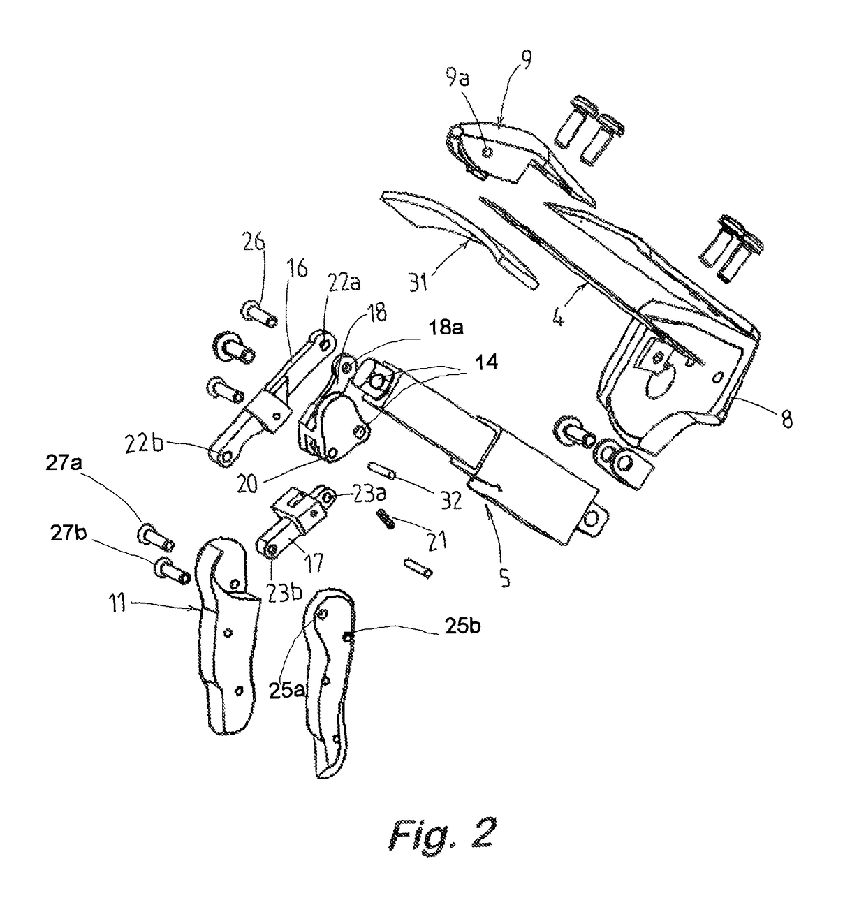
[0083]In one form, the invention relates to an automated hand, for use as a prosthetic hand or robotic hand. The automated hand comprises a support frame (where the hand attaches to a wrist portion), to which is attached a plurality of metacarpal members that are attached to a plurality of movable gripping members.

[0084]Each of the metacarpal members have a first end attached to the support frame (located at the base of the hand) via a universal joint. Each metacarpal member also has an opposing second end attached to a respective gripp...


PUM


Abstract

The invention relates to a gripping device, such as an automated hand, comprising a plurality of metacarpal members, each metacarpal member having a first end attached to a support frame via a universal joint and having a second end attached to a gripping member, wherein the metacarpal members are able to pivot upwardly, downwardly and laterally. Where adjacent metacarpal members together form a palm of the hand, the ability of the metacarpal members to move up, down and laterally helps the palm to grip an object and also helps the palm to withstand at least some forces from above, below and from the side.

Description

CROSS REFERENCE TO RELATED APPLICATIONS[0001]This application is a National Stage of International Application No. PCT / NZ2013 / 000140 filed Aug. 12, 2013, claiming priority based on U.S. Provisional Application No. 61 / 682,291 filed Aug. 12, 2012, the contents of all of which are incorporated herein by reference in their entirety.FIELD[0002]The present invention relates to a gripping device, such as an automated hand for use as a prosthetic or robotic hand.BACKGROUND[0003]Gripping devices in the form of automated hands are known in the fields of prosthetics and robotics.[0004]Many automated hands comprise a ‘palm’ and a plurality of gripping members or ‘fingers’. The fingers of the hand are adapted to move so that objects can be gripped between the fingers.[0005]United States patent publication no. US 2010 / 0259057 discloses a robotic hand with human-like fingers that are able to curl and flex using a series of pulleys and cables. United States patent application publication no. US 201...

Claims


Application Information

Patent Timeline
Patent Type & Authority Patents(United States)
IPC IPC(8): A61F2/54B25J15/00A61F2/70A61F2/58A61F2/50
CPCA61F2/583A61F2/586B25J15/0009A61F2002/701A61F2002/5038A61F2002/5079A61F2002/587A61F2002/5007
Inventor JURY, MATHEW JAMES
Owner 5TH ELEMENT
Learn More