
Method of 3D printing plastic molding compound on foil ply

Active Publication Date: 2017-11-14
LEONHARD KURZ GMBH & CO KG
View PDF15 Cites 3 Cited by
  • Summary
  • Abstract
  • Description
  • Claims
  • Application Information

AI Technical Summary

Benefits of technology

The patent describes a method for making molded objects using a plastic material that can be applied in layers to create decorative or functional structures inside the object. This method allows for greater design flexibility and the ability to compensate for any roughness or imperfections in the surface of the object. The use of solvents and coatings can also be used to further enhance the appearance of the molded object. Overall, this method allows for improved surface quality and a more intricate design process for molded objects.

Problems solved by technology

However, such production methods are limited in multiple aspects.
Because of the high temperatures and the high pressures during the injection molding, firstly the selection of the usable foil plies is restricted.
In particular foils having sensitive electronic functional layers or security elements cannot be used, since they would be destroyed under the injection molding conditions.
Furthermore, the freedom of design is restricted in the case of injection molding, since essentially only a substantially homogeneous plastic molding compound can be used.
Furthermore, molds, which are complex to produce and operate, are required as a tool for injection molding.
This requires high levels of investment and makes changes or individualizations of the parts to be produced problematic.
Furthermore, the molds must be replaced regularly, since a high level of wear is present due to the above-mentioned high pressures and temperatures.

Method used


Image

  • Method of 3D printing plastic molding compound on foil ply
  • Method of 3D printing plastic molding compound on foil ply
  • Method of 3D printing plastic molding compound on foil ply

Examples


Embodiment Construction

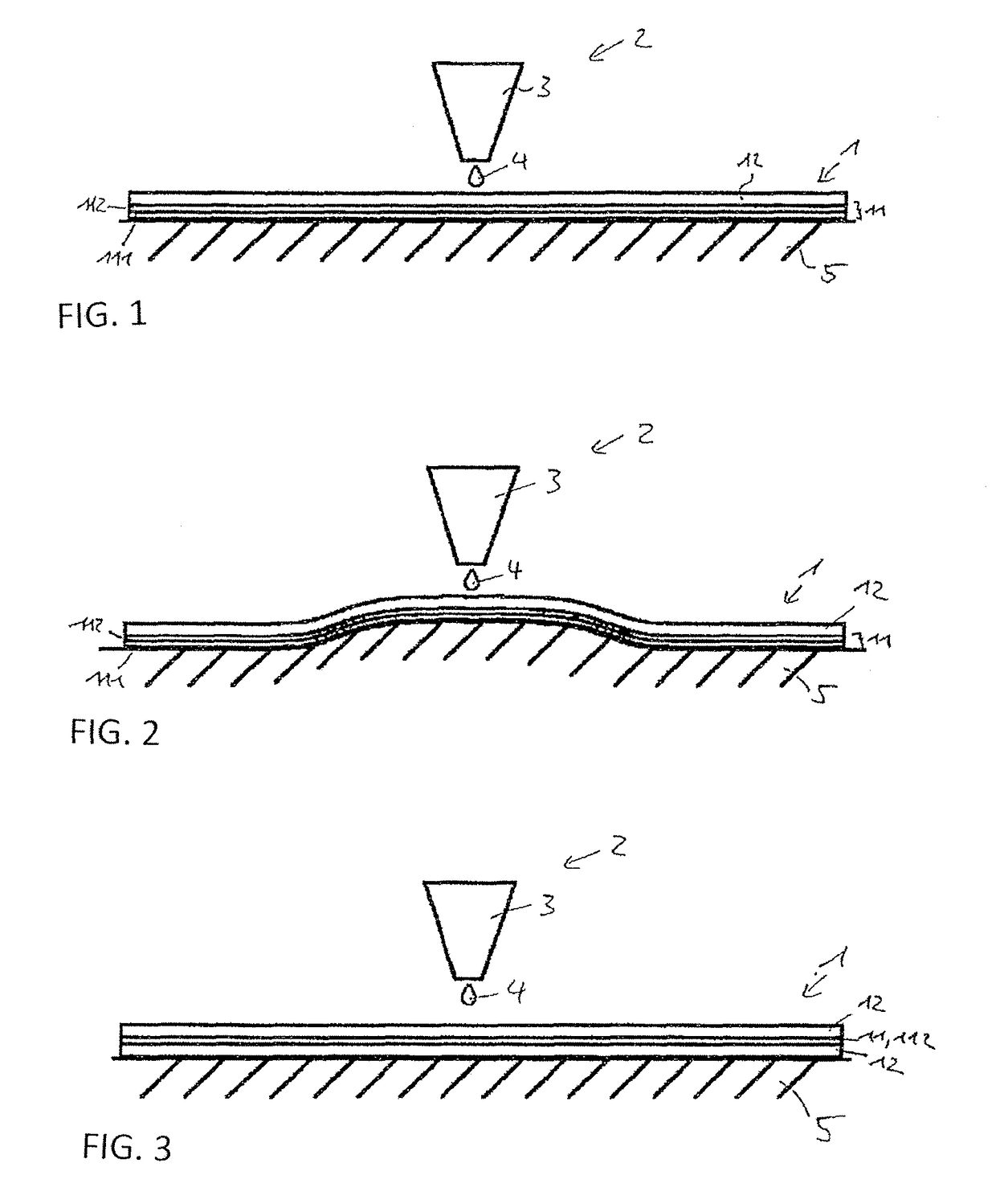
[0074]A molded body 1 comprises a foil ply 11, to which a plastic molding compound 12 is applied by means of a three-dimensional printing method.

[0075]The foil ply 11 can be a lamination foil or a transfer foil in this case. In the latter case, the foil ply 11 comprises a carrier ply 111, on which the transfer ply 112, which finally remains in the molded body, is attached so it is detachable.

[0076]A layer thickness of the foil ply 11 is preferably 10 μm to 250 μm, particularly preferably 20 μm to 250 μm.

[0077]The foil ply 11 can have an adhesion-promoter layer, which is not shown in the figures. The plastic molding compound 12 is then applied to this adhesion-promoter layer. It can be a plastic which is chemically related to the plastic molding compound in this case and / or a heat-activatable adhesive, for example, adhesive based on polyvinyl chloride (PVC) or based on acrylics or adhesive based on mixtures of PVC and acrylics.

[0078]Furthermore, the foil ply can comprise decorative o...


PUM

PropertyMeasurementUnit
Temperatureaaaaaaaaaa
Thicknessaaaaaaaaaa

Abstract

A method for producing a molded body having the following steps: a) providing a foil ply; b) applying a plastic molding compound in a predefined three-dimensional shape onto the foil ply by means of a three-dimensional printing method.

Description

[0001]This application claims priority based on German Application No. DE102014104321.9, filed on Mar. 27, 2014.BACKGROUND OF THE INVENTION[0002]The invention relates to a method for producing a molded body and also a molded body produced in this manner.[0003]To combine decorative or functional elements with plastic parts, accommodating foil plies with such elements in injection molded parts is known. In this case, such a foil ply is laid in an injection mold and fixed therein. Subsequently, a plastic molding compound is injected into the injection mold, where it bonds to the foil ply and cures. A known method for this purpose is the so-called in-mold decoration method (IMD) or the insert molding method.[0004]However, such production methods are limited in multiple aspects. Because of the high temperatures and the high pressures during the injection molding, firstly the selection of the usable foil plies is restricted. In particular foils having sensitive electronic functional layer...

Claims


Application Information

Patent Timeline
IPC IPC(8): B29C65/48B44C3/02B29C67/00B33Y10/00B33Y30/00B33Y40/00B33Y99/00B32B15/08B32B15/085B32B15/00B32B15/04B32B15/082B32B7/12B32B15/10B29C65/00B32B9/04B29C37/00B05D1/26B05D7/14B05D3/00B05D1/02B33Y80/00
CPCB29C64/147B29C64/165B29C65/48B05D1/02B05D1/26B05D3/002B05D7/14B29C37/0025B29C65/4815B29C66/02B29C66/41B29C66/70B29C66/712B29C66/7232B29C66/72327B29C66/742B29C66/7484B29C66/7487B32B7/12B32B9/041B32B9/042B32B9/045B32B15/00B32B15/04B32B15/08B32B15/082B32B15/085B32B15/10B33Y10/00B33Y30/00B33Y40/00B33Y99/00B44C3/02B29C64/393Y10T442/20B05D2201/02B05D2202/00B05D2203/20B05D2203/24B05D2502/005B05D2507/005B29C2795/00B32B2255/06B32B2255/08B32B2255/10B32B2255/26B32B2255/28B33Y80/00Y10T428/24612Y10T428/24802Y10T428/24901Y10T428/264Y10T428/31507Y10T428/31696Y10T428/31895Y10T428/31931B29C64/112B29C64/40B29C64/106B33Y40/20
Inventor PFORTE, KLAUSHAHN, MARTIN
Owner LEONHARD KURZ GMBH & CO KG
Learn More