Light emitting diode light strip unit structure

a technology of light emitting diodes and light strips, which is applied in the direction of electroluminescent light sources, lighting and heating apparatuses, electric lighting sources, etc., can solve the problems of inability to supply voltage to leds, prone to burn up of led chips, and a lot of time and work, so as to save the cost of driving the circuit, improve the light source, and facilitate repair

Inactive Publication Date: 2017-11-14
UBLEDS
View PDF10 Cites 5 Cited by
  • Summary
  • Abstract
  • Description
  • Claims
  • Application Information

AI Technical Summary

Benefits of technology

[0005]The primary object of the present invention is to provide a light emitting diode light strip unit structure. The light emitting diode light strip unit structure comprises an illuminating light strip unit. The illuminating light strip unit comprises a base strip, a plurality of illuminating members, and a drive illuminating member. The base strip is made of an insulation material and provided with a conducting circuit thereon. Two ends of the conducting circuit are provided with at least one power supply voltage contact, a working voltage contact, a signal input contact, a signal output contact, and a grounding contact on the base strip. The illuminating members each comprise at least one light emitting diode disposed on the base strip. The illuminating members are connected with the conducting circuit in series to get supply voltage through the power supply voltage contact. The drive illuminating member comprises at least one built-in LED illuminating chip and a built-in IC drive chip. The LED illuminating chip and the illuminating members are connected in series through the conducting circuit. The IC drive chip is electrically connected with the LED illuminating chip as a drive circuit of the LED illuminating chip and the illuminating members. Through the conducting circuit, the working voltage contact gets working electricity, the signal input contact receives an external control signal, the signal output contact sends the control signal out, and the grounding contact and a power source form a ground loop. The illuminating light strip unit can be connected with the power source and receive the control signal independently as a light source. A plurality of illuminating light strip units are assembled and electrically connected with each other. The power supply voltage contacts and the working voltage contacts of the illuminating light strip units are electrically connected with the external power source to get working electricity. When the grounding contacts of the illuminating light strip units complete the ground connection, the signal output contacts and the signal input contacts of the illuminating light strip units are electrically connected. One of the signal input contacts of the illuminating light strip units is predetermined to receive the control signal to form various types or forms (area) of light sources. Each illuminating light strip unit has the built-in IC drive chip of the drive illuminating member thereon to drive the illuminating members at a short distance for forming various types or forms of light sources. This way saves the cost to drive the circuit and enables each illuminating member to work under a stable working voltage so as to provide a better light source. The illuminating light strip units are assembled to complete various types or forms of light sources. Each of the illuminating light strip units can illuminate independently. It is convenient to repair each illuminating light strip unit. The present invention is cost-effective.

Problems solved by technology

If the supply voltage is not stable, the LED chip is prone to burn up or may have the problems of light attenuation, scintillation, and so on.
When the assembly of multiple light strips is used as a light source, it takes a lot of time and work.
Sometimes, the supply voltage to the LED is not stable.
This will impact the quality of the light source.
If the voltage is increased or decreased, the light may be burned up or have the problems of light attenuation, scintillation, and so on.
This causes difficulties in maintenance.

Method used


Image

  • Light emitting diode light strip unit structure
  • Light emitting diode light strip unit structure
  • Light emitting diode light strip unit structure

Examples


Embodiment Construction

[0014]Embodiments of the present invention will now be described, by way of example only, with reference to the accompanying drawings.

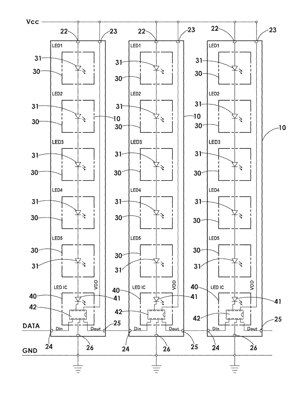
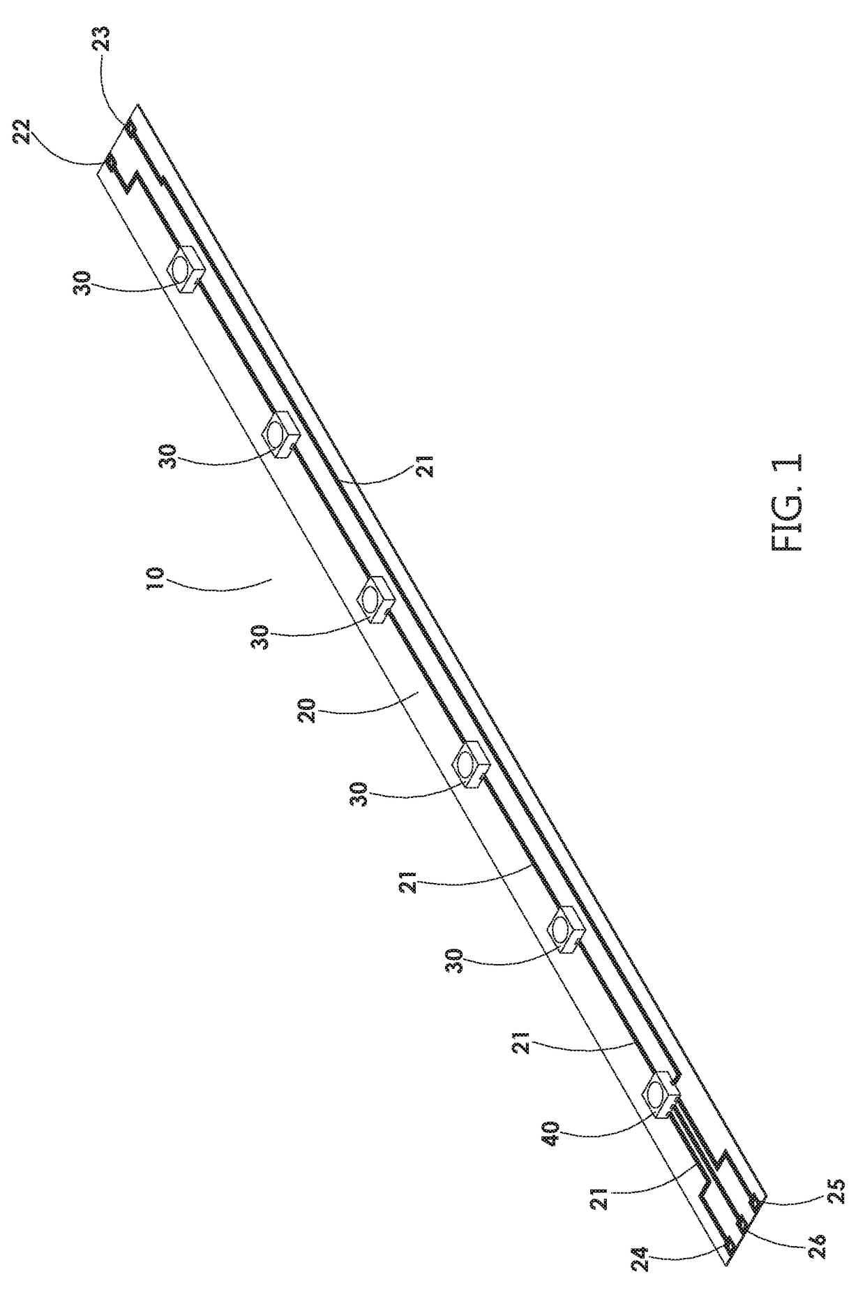
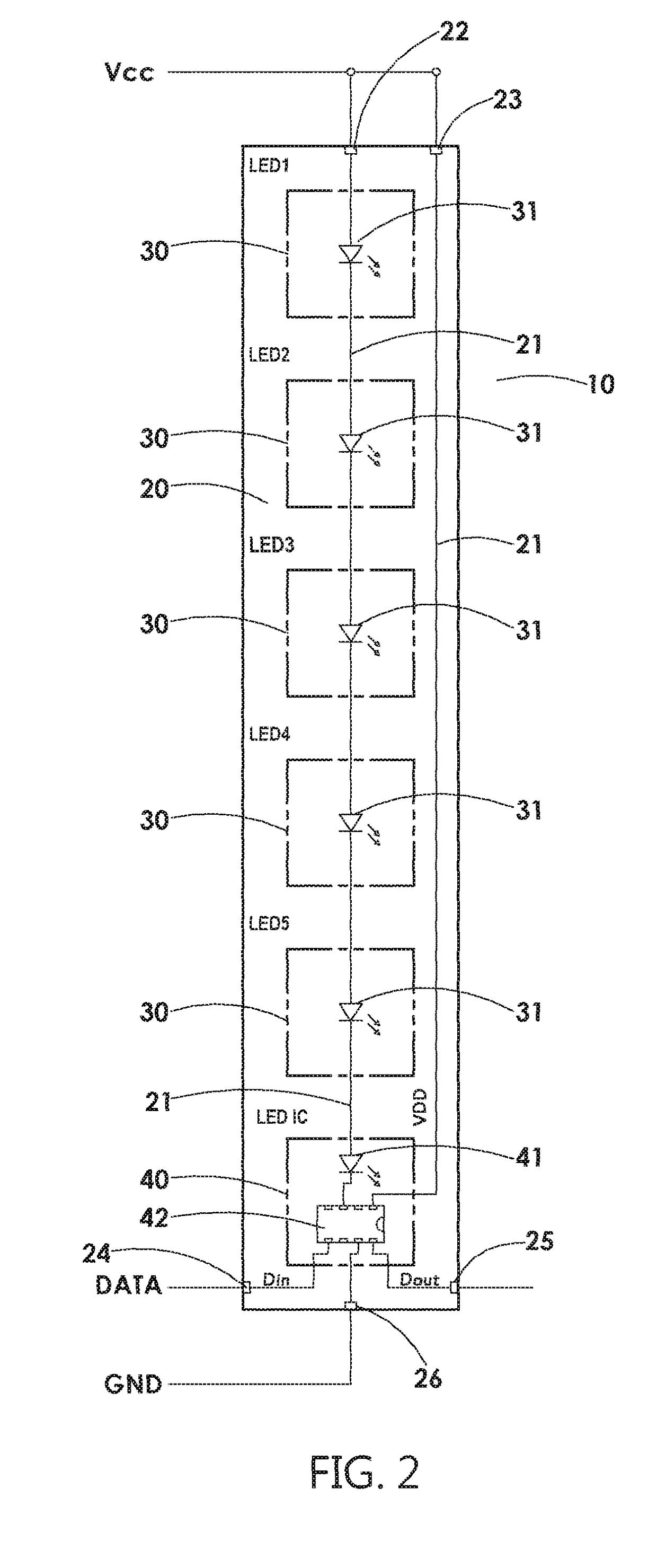
[0015]As shown in FIG. 1 and FIG. 2, the present invention discloses a light emitting diode light strip unit structure comprises an illuminating light strip unit 10. The illuminating light strip unit 10 comprises a base strip 20, a plurality of illuminating members 30, and a drive illuminating member 40. The base strip 20 is made of an insulation material and provided with a conducting circuit 21 thereon. Two ends of the conducting circuit 21 are provided with at least one power supply voltage contact 22, a working voltage contact 23, a signal input contact 24, a signal output contact 25, and a grounding contact 26 on the base strip 20. The illuminating members 30 (LEDs 1-5) each comprise at least one light emitting diode (LED) 31 disposed on the base strip 20. The illuminating members 30 are connected with the conducting circuit 21 in series to get s...


PUM


Abstract

A light emitting diode light strip unit structure is provided. The light emitting diode light strip unit structure includes an illuminating light strip unit which can be connected with an external power source and receive an external control signal independently as a light source. A plurality of illuminating light strip units are assembled and electrically connected with each other. Power supply voltage contacts and working voltage contacts of the illuminating light strip units are electrically connected with the power source to get working electricity. When grounding contacts of the illuminating light strip units complete the ground connection, signal output contacts and signal input contacts of the illuminating light strip units are electrically connected. One of the signal input contacts of the illuminating light strip units is predetermined to receive the control signal to form various types or forms (area) of light sources.

Description

BACKGROUND OF THE INVENTION[0001]1. Field of the Invention[0002]The present invention relates to a light emitting diode light strip unit structure, and more particularly to a light strip unit used as a light source. The light strip unit can save the cost to drive the circuit and provide a stable voltage to illuminating members. The light strip unit can illuminate independently, which is beneficial for maintenance and repair.[0003]2. Description of the Prior Art[0004]With the rise of environmental awareness and energy-saving, the developments of various types of electronic devices gradually comply with the requirements environmental protection and energy-saving, especially for the requirement of lighting or a light source. The main reason is that lighting or a light source is indispensable in our life. Based on the concept of environmental protection and energy-saving, illuminating devices, such as traditional light tubes, light bulbs, and the like, are gradually replaced with LED li...

Claims


Application Information

Patent Timeline
Patent Type & Authority Patents(United States)
IPC IPC(8): H05B33/08F21V23/00F21S4/22F21V23/02H05B44/00
CPCF21V23/02F21S4/22F21V23/005H05B33/083H05B33/0857H05B33/086H05B33/0812H05B33/0827H05B33/0803H05B45/20H05B45/46H05B45/00H05B45/48
Inventor HSUE, SHOUWENCHANG, HAN-SHENGCHIU, YU-FENG
Owner UBLEDS
Why Eureka
Try Eureka