
Battery pack with shock absorber

a battery pack and shock absorber technology, applied in the field of batteries, can solve the problems of increasing the resistance of the charge-discharge path, affecting the efficiency of the battery pack, and the most deteriorating characteristic among reliability conditions, so as to prevent damage or deformation of the bare cell

Active Publication Date: 2017-11-14
SAMSUNG SDI CO LTD
View PDF27 Cites 0 Cited by
  • Summary
  • Abstract
  • Description
  • Claims
  • Application Information

AI Technical Summary

Benefits of technology

[0008]When a weight and volume of a battery pack are increased, the most deteriorating characteristic from among reliability conditions is a falling characteristic. This is because a shock at the free fall is increased according to an increase of the volume of the battery pack. This causal relationship highly damages the battery pack in a free fall test, and the biggest problem is that resistance of a charge-discharge path, which directly affects an efficiency of the battery pack, is increased.
[0009]One or more embodiments of the present invention include a battery pack of which reliability with respect to an external shock is increased.
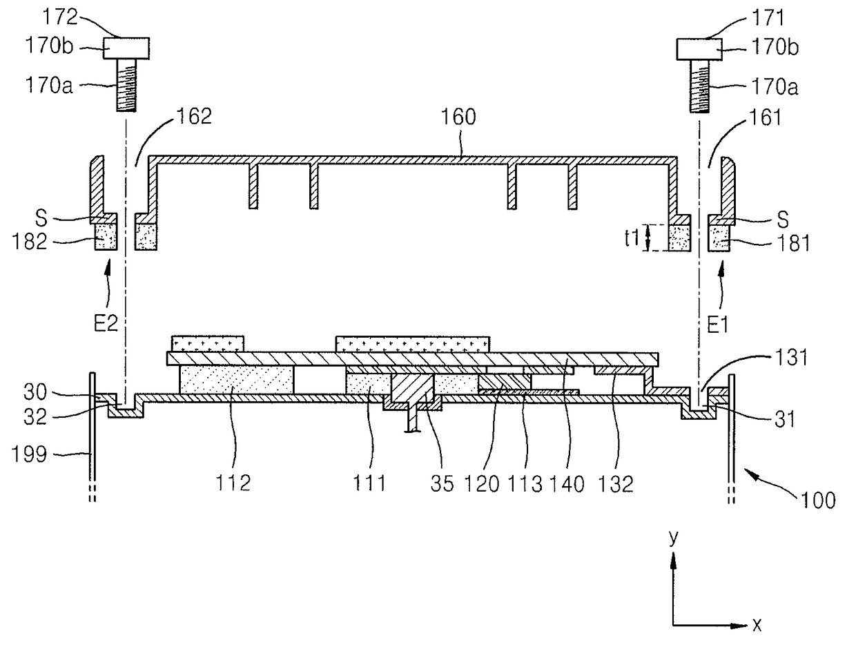
[0017]According to one or more embodiments of the present invention, when an upper cover is coupled to a bare cell capable of being charged and discharged, and / or a lead member contacting the bare cell, a shock absorbing layer is interposed therebetween. By doing so, although a strong external shock such as a free fall is applied via the upper cover, the shock absorbing layer absorbs or relieves a shock conveyed to the bare cell and / or the lead member, so that it is possible to prevent a damage or deformation of the bare cell and the lead member. Coupling between the bare cell and the lead member that form an electric contact is protected against the strong external shock, and the deformation due to the strong external shock is prevented so that electric resistance of a charge-discharge current path formed by the lead member may be maintained at a low level.

Problems solved by technology

When a weight and volume of a battery pack are increased, the most deteriorating characteristic from among reliability conditions is a falling characteristic.
This causal relationship highly damages the battery pack in a free fall test, and the biggest problem is that resistance of a charge-discharge path, which directly affects an efficiency of the battery pack, is increased.

Method used


Image

  • Battery pack with shock absorber
  • Battery pack with shock absorber
  • Battery pack with shock absorber

Examples

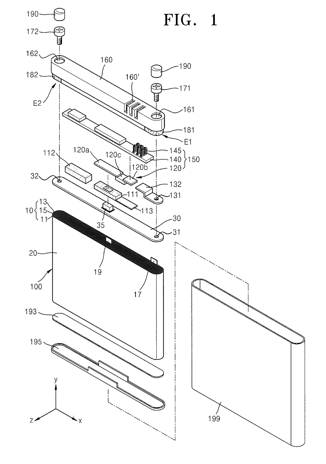
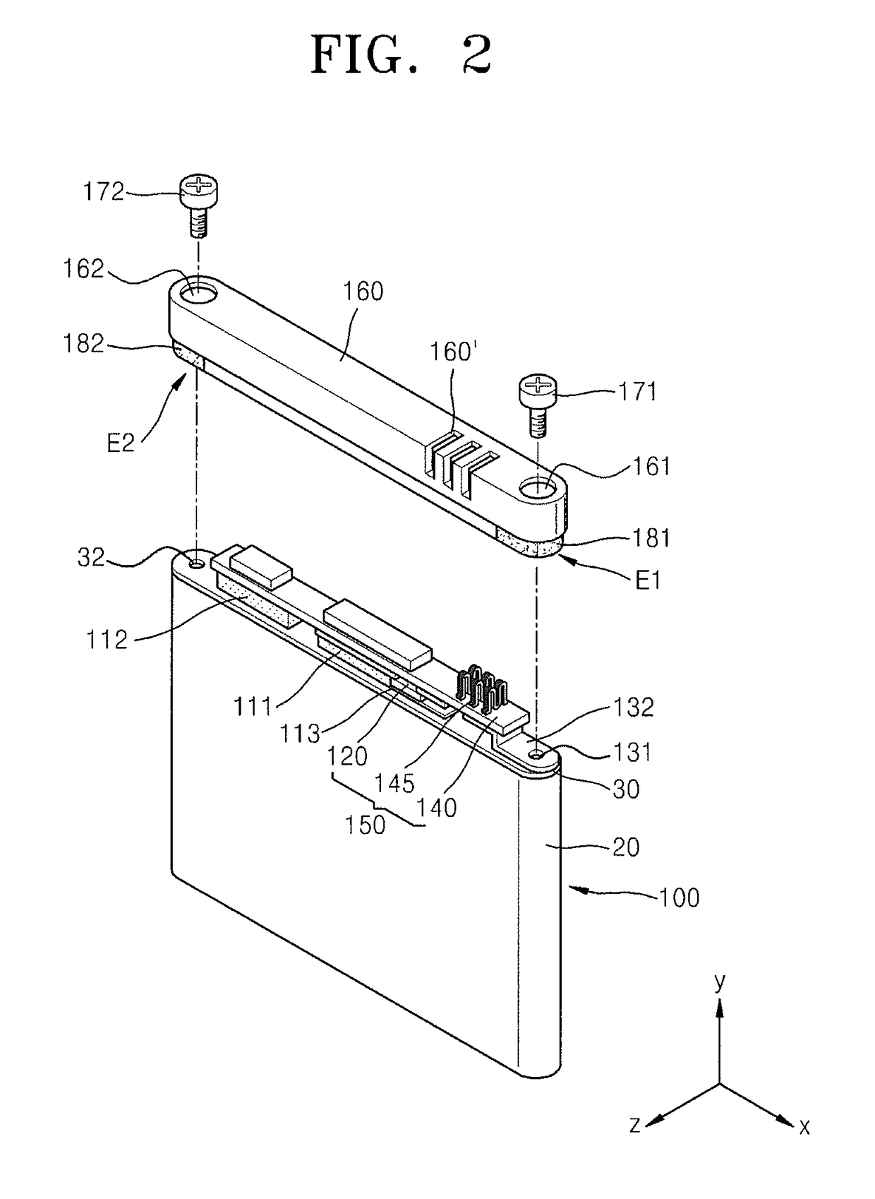

Embodiment Construction

[0027]Reference will now be made in detail to embodiments, examples of which are illustrated in the accompanying drawings.

[0028]As used herein, the term “and / or” includes any and all combinations of one or more of the associated listed items.

[0029]FIGS. 1 through 3 are exploded perspective views of a battery pack according to an embodiment of the present invention.

[0030]The battery pack includes a bare cell 100 capable of being charged and discharged, a protective circuit module (PCM) 150 mounted on the bare cell 100 so as to control charging and discharging operations of the bare cell 100, and an upper cover 160 coupled with the bare cell 100 so as to receive the PCM 150.

[0031]The bare cell 100 is a rechargeable secondary battery, may be formed of a lithium-ion battery, and has a structure in which an electrode assembly 10 including a positive electrode plate 11, a negative electrode plate 13, and a separator 15 is placed into contact with an electrolyte and then sealed in a can 20...


PUM

PropertyMeasurementUnit
thicknessaaaaaaaaaa
stabilityaaaaaaaaaa
weightaaaaaaaaaa

Abstract

A battery pack includes a bare cell including an electrode assembly, a can housing the electrode assembly; and a cap plate sealing an open end of the can; a protective circuit module on the bare cell and including a lead member electrically coupling the protective circuit module to the bare cell; an upper cover coupled to the bare cell and covering the protective circuit module; and a shock absorber between the upper cover and the lead member.

Description

CROSS-REFERENCE TO RELATED APPLICATIONS[0001]This application claims priority to and the benefit of U.S. Provisional Application No. 61 / 377,885, filed on Aug. 27, 2010, in the United States Patent and Trademark Office, the disclosure of which is incorporated herein in its entirety by reference.BACKGROUND[0002]1. Field[0003]One or more embodiments of the present invention relate to a battery pack.[0004]2. Description of the Related Art[0005]There is an increasing demand for using a secondary battery as an energy source according to technology development and an increase of the manufacture thereof with respect to mobile devices such as mobile phones, notebooks, and the like. Recently, as a substitute energy source for replacing fossil fuel, secondary batteries have been studied and developed to be used in electric vehicles and hybrid vehicles.[0006]In general, a secondary battery includes an inflammable material, and in consideration of stability of the secondary battery, the secondar...

Claims


Application Information

Patent Timeline
Patent Type & Authority Patents(United States)
IPC IPC(8): H01M2/04H01M10/04H01M10/42H01M2/10H01M50/147H01M50/202H01M50/242H01M50/271
CPCH01M2/0404H01M2/0473H01M2/0478H01M10/425H01M2/10H01M10/0431H01M2/0482Y02E60/10H01M50/147H01M50/15Y02P70/50H01M50/202H01M50/242H01M50/271
Inventor BAEK, WOON-SEONG
Owner SAMSUNG SDI CO LTD
Learn More