Reciprocating cutting tool

a cutting tool and reciprocating technology, applied in the field of cutting tools, can solve the problems of similar problems presented with other cutting tools

Active Publication Date: 2017-11-21
ROBERT BOSCH GMBH
View PDF12 Cites 570 Cited by
  • Summary
  • Abstract
  • Description
  • Claims
  • Application Information

AI Technical Summary

Benefits of technology

[0005]The present invention provides a cutting tool having at least one driven blade movable between two predefined points of maximum travel, the tool further comprising a prime mover adapted to cause movement of the said at least one movable blade between said points of maximum travel; characterized in that the cutting tool is further provided with a control means which causes a change of direction in the movement of the at least one movable blade at a point intermediate the points of maximum travel in response to an event sensed by the control means.

Problems solved by technology

Hedgecutters frequently suffer in use from a problem of blocked cutting blades when they encounter a twig or branch whose size or density exceeds the capacity of the blades.
Similar problems are presented with other cutting tools.

Method used


Image

  • Reciprocating cutting tool
  • Reciprocating cutting tool
  • Reciprocating cutting tool

Examples


Embodiment Construction

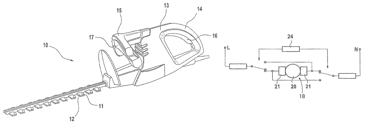
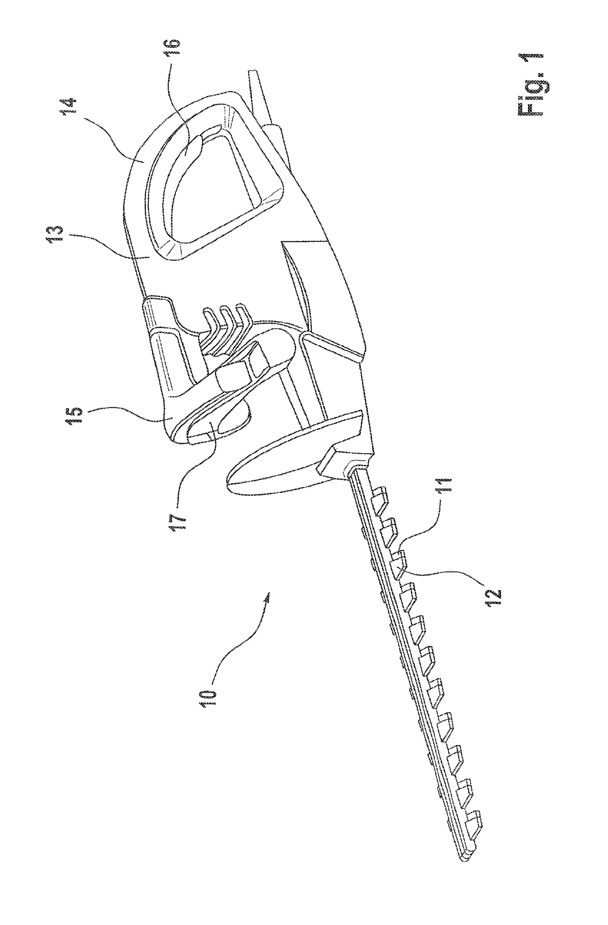
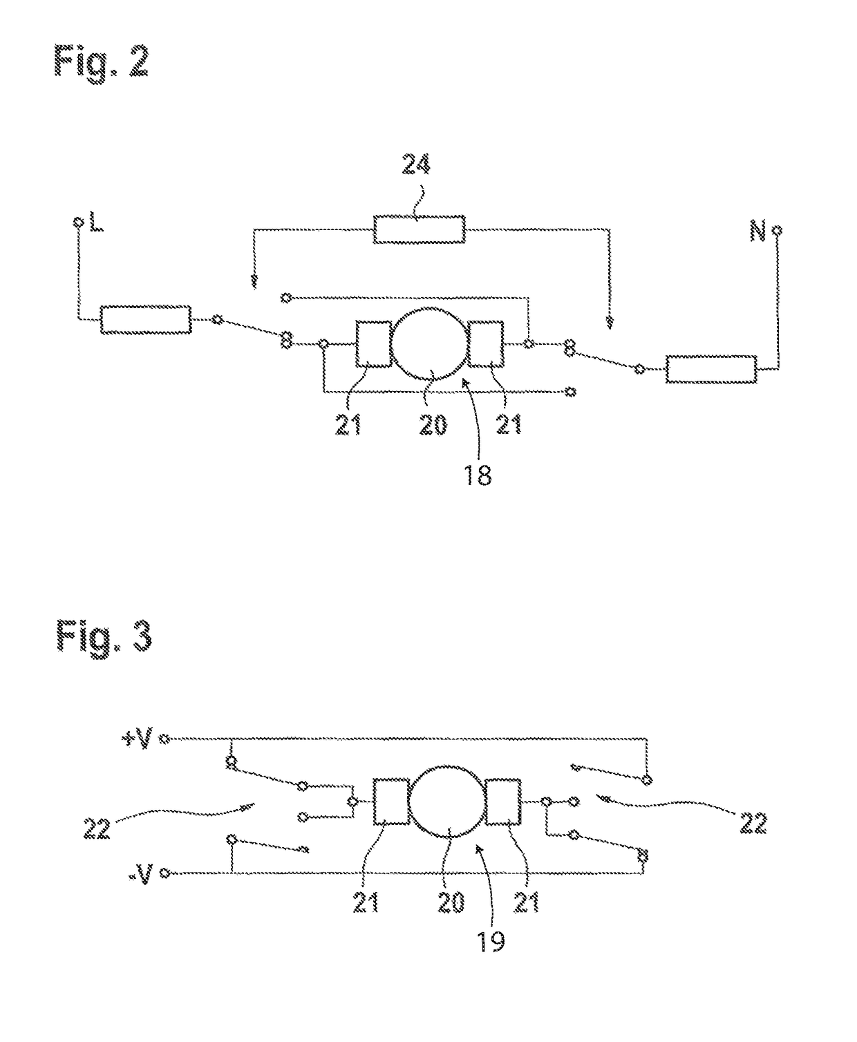
[0021]A typical vegetation cutter in accordance with the present invention is in the form of an electric hedgecutter 10 having a bottom blade 11 and an upper blade 12 caused to reciprocate simultaneously and in an equal and opposite manner with respect to the housing and hence also to each other by means of an electric motor M housed in a housing unit 13. The housing unit 13 includes two grips 14, 15, each associated with a switch arrangement 16, 17. This switching configuration provides a safety feature requiring both left and right hands of the operator to be in position and actuating their respective switches in order to supply an electric current to the motor. Accordingly, the blades cannot be put into an operating configuration unless both hands are away from the blades.

[0022]The motor acts to reciprocate the moving blades 11,12 in a conventional manner through suitable gearing as required.

[0023]In accordance with the present invention, it is possible to drive the reciprocating...


PUM

PropertyMeasurementUnit
currentaaaaaaaaaa
speedaaaaaaaaaa
sizeaaaaaaaaaa

Abstract

The present invention relates to cutting tools, in particular, to control systems for cutters such as vegetation cutters, especially hedge cutters or trimmers (10). Hedge cutters (10) frequently suffer in use from a problem of blocked cutting blades when they encounter a twig or branch whose size or density exceeds the capacity of the blades. We describe a vegetation cutting apparatus (10) having a plurality of cutting blades (11,12), at least one of which blades (11,12) is drivable by an electric motor. At least one driven blade (11,12) is movable between two predefined points of maximum travel. The apparatus (10) includes a control mechanism which causes a change of direction in the movement of the at least one movable blade at a point intermediate the points of maximum travel in response to an event sensed by the control mechanism.

Description

CROSS-REFERENCE[0001]The invention described and claimed hereinbelow is also described in EP 07104239, filed on Mar. 14, 2007. This European Patent Application, whose subject matter is incorporated here by reference, provides the basis for a claim of priority of invention under 35 U.S.C. 119 (a)-(d).BACKGROUND OF THE INVENTION[0002]The present invention relates to cutting tools. In particular, it relates to control systems for vegetation cutters especially hedge cutters or trimmers.[0003]Hedgecutters comprise two elongate blades which reciprocate with respect to each other. Either one blade is fixed and the other caused to reciprocate or both blades caused to reciprocate in an equal and opposite manner. The blades are driven by means of a cam element driven by the output shaft of an electric motor or small engine. One such cutter is described in JP2005269972, which hedge cutter also includes a switch allowing the user to reverse the direction of motion of one of the blades.[0004]Hed...

Claims


Application Information

Patent Timeline
Patent Type & Authority Patents(United States)
IPC IPC(8): A01G3/053A01D34/408A01D34/135A01D34/37A01D34/30A01G3/04
CPCA01G3/053A01D34/135A01D34/30A01D34/408A01D34/37Y10T83/536A01G2003/0461Y10T83/525
Inventor SIMPSON, PETERGLAUNING, RAINER
Owner ROBERT BOSCH GMBH
Why Eureka
Try Eureka