Instrument for reshaping the head of a femur

a cutting device and head technology, applied in the field of orthopedic cutting devices, can solve the problems of inability to properly position and align the tools with respect to the cut created by the prior tool, inability to achieve the desired effect, and inability to cause the misalignment of the prosthesis. the effect of reducing the possibility of causing the misalignment of the prosthesis

Active Publication Date: 2017-11-21
WILSON GREATBATCH LTD
View PDF57 Cites 0 Cited by
  • Summary
  • Abstract
  • Description
  • Claims
  • Application Information

AI Technical Summary

Benefits of technology

[0015]Rotation of the cutting instrument of the present invention against a bone causes the end of the bone to be shaped into the desired multi-faceted form shown in FIG. 4. Thus, unlike the prior art, the femoral head is reshaped into a desired form in a single cutting motion at one time. Since all the cutting blades are incorporated into one tool, the possibility of causing prosthesis misalignment is reduced, thereby improving patient outcomes and patient mobility.

Problems solved by technology

While it has been shown that total hip replacement surgery is effective for some patients, a total hip replacement surgical procedure may cause neuromuscular damage.
Furthermore, removing the end of the femur may cause bleeding problems, infection, or other complications that are not desirable.
Utilization of three separate cutting tools creates an inherent risk that the tools might not be properly positioned and aligned with respect to the cut created by the prior tool.
Therefore, there is a possibility that the head of the femur might not be properly shaped for proper positioning of the femoral head prosthetic.
This interface between the handle and the cutting tool may not be secure.
Therefore, because the handle may not be adequately positioned and secured to the cutting tool, the cutting surface of the tool may be askew from its proper position or the cutting surface may shift during use.
Therefore, possible misalignment between the handle and the cutting instrument may result in an improperly shaped femur.
In addition, a slight misalignment in positioning the cutting surface of the cutting tool to the bone by the surgeon of any one of the three prior art cutting tools, could also result in an improperly shaped femur, thereby leading to poor positioning of the femoral head prosthesis.
In either case, an improperly fit femoral head prosthesis may negatively affect patient mobility and also require that the patient undergo additional surgical procedures to correct the misalignment.

Method used


Image

  • Instrument for reshaping the head of a femur
  • Instrument for reshaping the head of a femur
  • Instrument for reshaping the head of a femur

Examples


Embodiment Construction

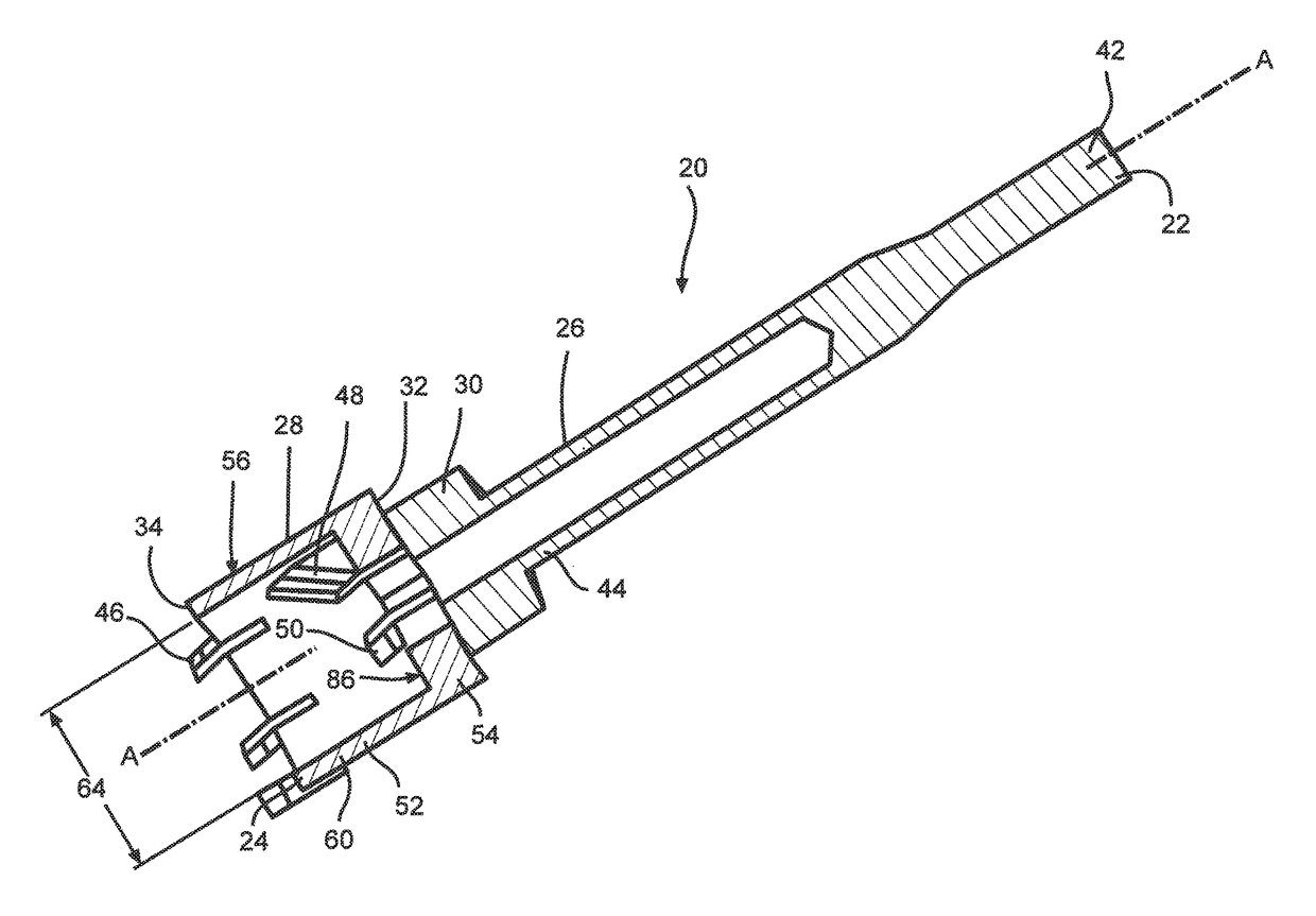
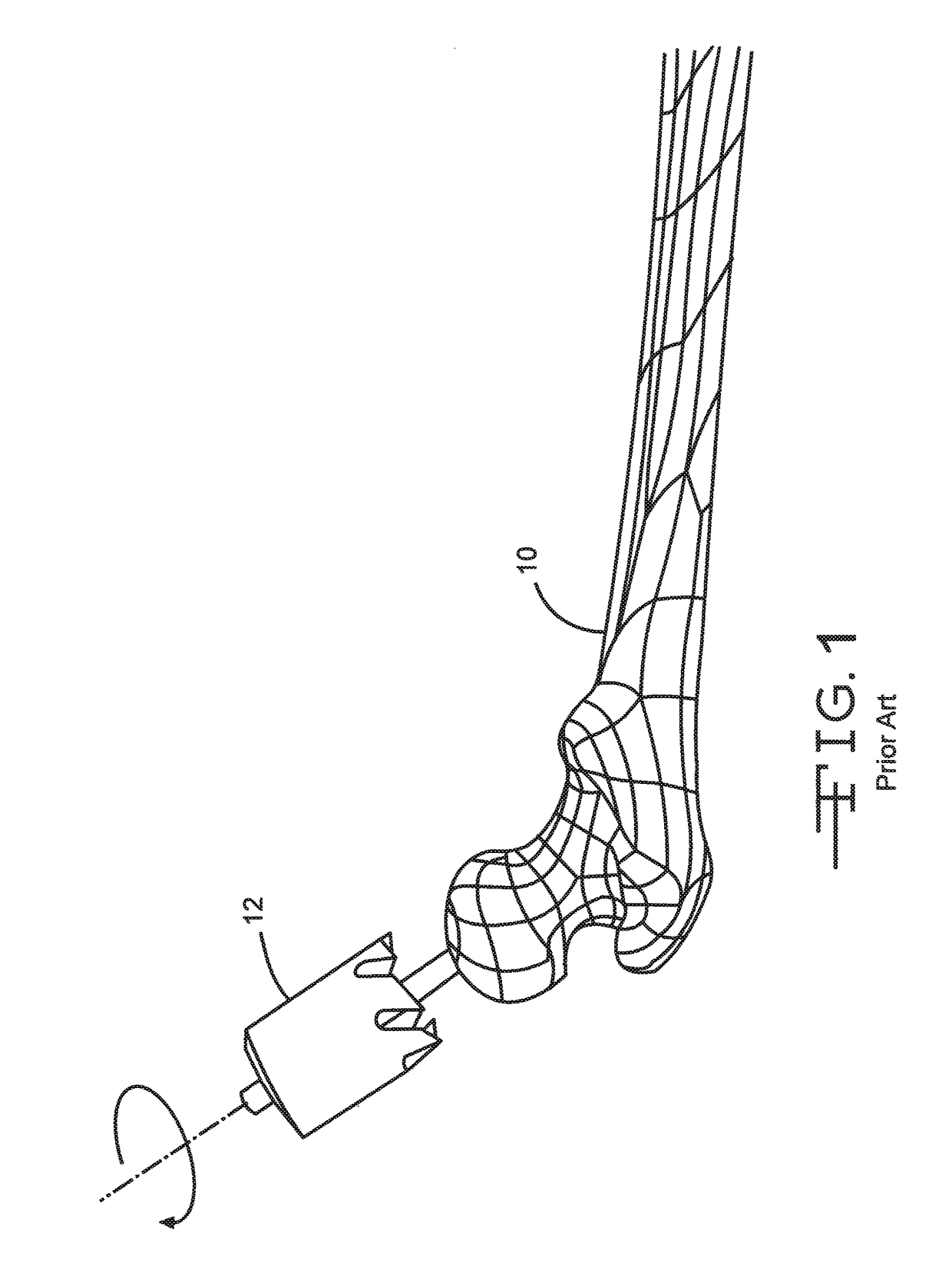
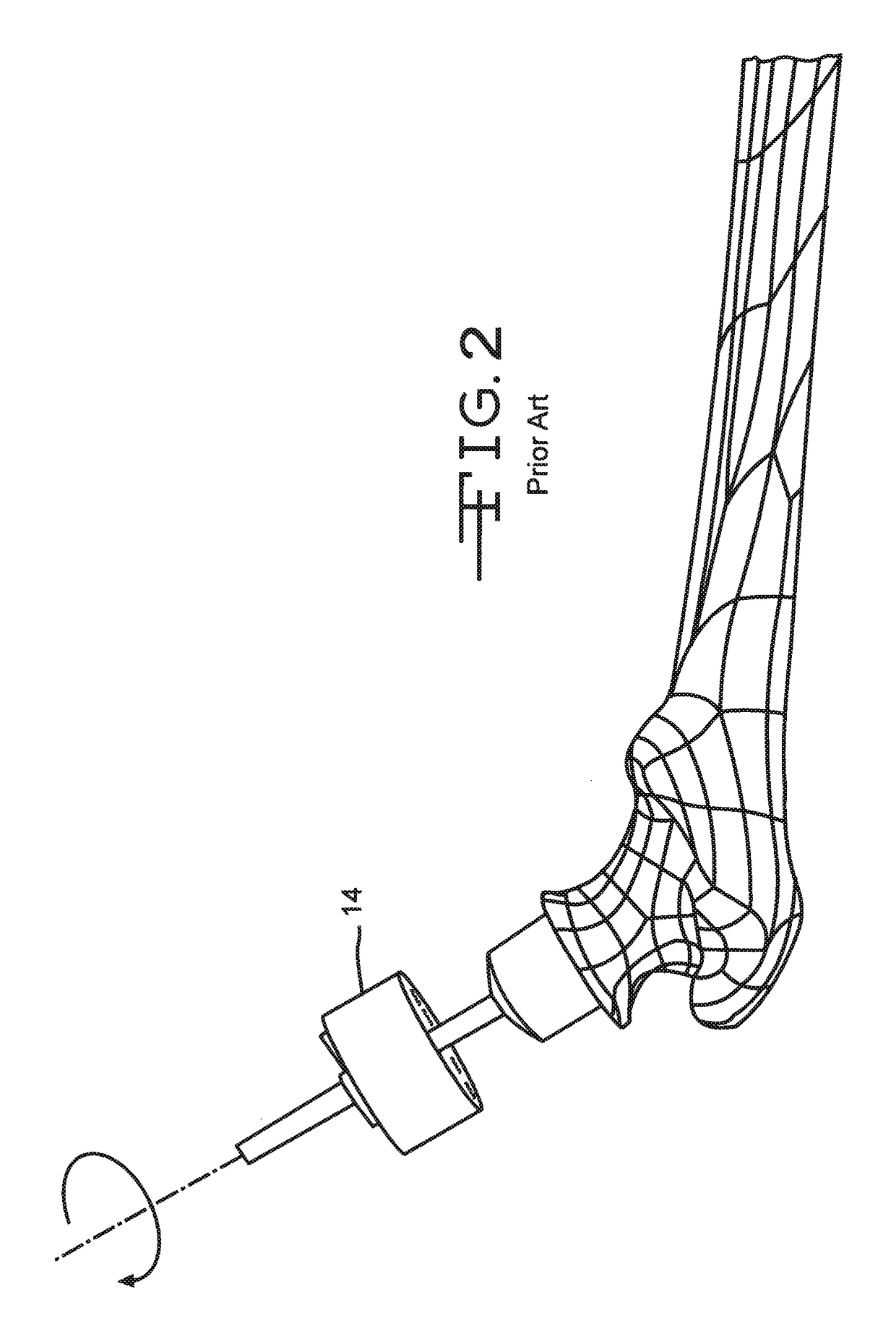
[0036]Now turning to the figures, FIGS. 5, 5A, 6 and 13 illustrate an embodiment of a bone cutter 20 of the present invention. As shown, the bone cutter comprises a bone cutter proximal end 22 that extends to a bone cutter distal end 24 along a longitudinal axis A-A. As illustrated, the bone cutter 20 of the present invention comprises a housing 26 that is designed to hold and secure a plurality of cutting blades that are used to cut and reshape the end of a bone 10, more specifically a femur (FIG. 4).

[0037]In an embodiment, the housing 26 comprises a first housing segment 28 that is connected to a second housing segment 30. The first housing segment 28 comprises a first blade holder proximal end 32 that extends along longitudinal axis A-A to a first housing segment distal end 34. The second housing segment 30 comprises a second housing segment proximal end 36 that extends along longitudinal axis A-A to a second housing segment distal end 38. A shaft portion 40 having spaced apart p...


PUM


Abstract

An orthopedic cutting tool for reshaping the end of a femur is described. The cutting tool comprises three separate cutting blades that are positioned within different locations within a housing to reshape the end of the femur to thus receive a femur head prosthetic. The cutting tool forms the reshaped femur end in one cutting motion.

Description

CROSS REFERENCE TO RELATED APPLICATION[0001]This application claims priority to U.S. provisional application Ser. No. 61 / 811,453, filed Apr. 12, 2013.FIELD OF THE INVENTION[0002]The present invention relates to the art of orthopedic cutting devices, more particularly, to an orthopedic cutting device designed to remove bone and tissue from a femur.BACKGROUND OF THE INVENTION[0003]Hip arthroplasty involves removing a diseased hip joint and replacing it with an artificial joint. In one procedure, commonly referred to as a total hip replacement, the head of the femur is removed and a femoral stem having a femoral head prosthesis end is positioned within the end of the bone. The femoral head is received within a prosthetic cup positioned within the acetabulum. While it has been shown that total hip replacement surgery is effective for some patients, a total hip replacement surgical procedure may cause neuromuscular damage. Furthermore, removing the end of the femur may cause bleeding pro...

Claims


Application Information

Patent Timeline
Patent Type & Authority Patents(United States)
IPC IPC(8): A61B17/16
CPCA61B17/1668
Inventor VICTOR, GARY C.
Owner WILSON GREATBATCH LTD
Why Eureka
Try Eureka