Check patentability & draft patents in minutes with Patsnap Eureka AI!

Rotation detection device and bearing unit equipped with rotation detection device

a detection device and bearing technology, applied in measurement devices, speed/acceleration/shock measurement, instruments, etc., can solve the problems of increased mounting space or mounting cost, inability to correct, and inability to include actual encoder output, so as to avoid the influence of signal change, stably detect the rotational speed, and high accuracy

Active Publication Date: 2017-11-21
NTN CORP
View PDF17 Cites 3 Cited by
  • Summary
  • Abstract
  • Description
  • Claims
  • Application Information

AI Technical Summary

Benefits of technology

Enables accurate detection of rotational speed and position with reduced complexity and cost by using internal error correction mechanisms, eliminating the need for additional sensors and improving mounting accuracy.

Problems solved by technology

Meanwhile, an actual encoder output includes errors that occur in association with one rotation of the shaft, such as, for example, magnetization pitch errors regarding the magnetic encoder, pitch errors due to deformation or misalignment in mounting the encoder, and the like.
However, even if an error pattern corresponding to one rotation is stored in order to correct such errors, if a rotational position serving as the reference for the error pattern is not known, correction cannot be made.
In order to output the Z phase signal, an additional sensor or a special encoder is needed, which poses a problem of increased mounting space or increased mounting costs.

Method used


Image

  • Rotation detection device and bearing unit equipped with rotation detection device
  • Rotation detection device and bearing unit equipped with rotation detection device
  • Rotation detection device and bearing unit equipped with rotation detection device

Examples


Embodiment Construction

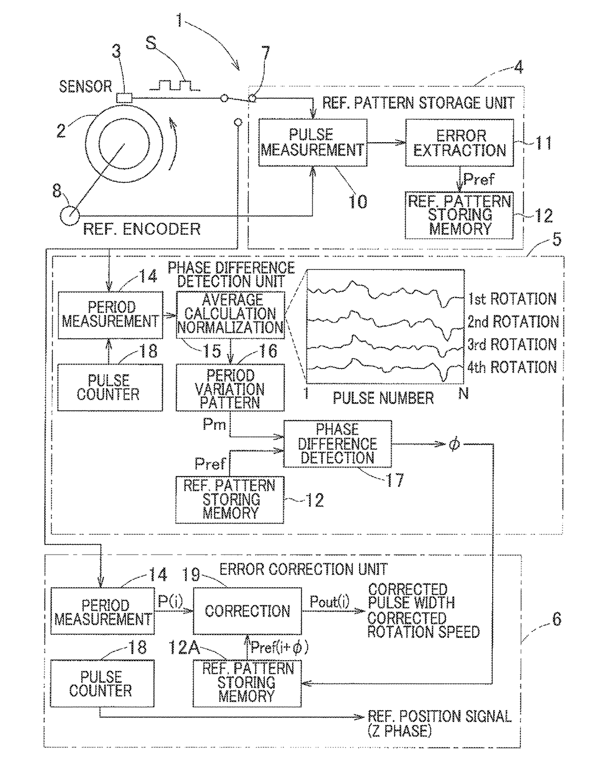
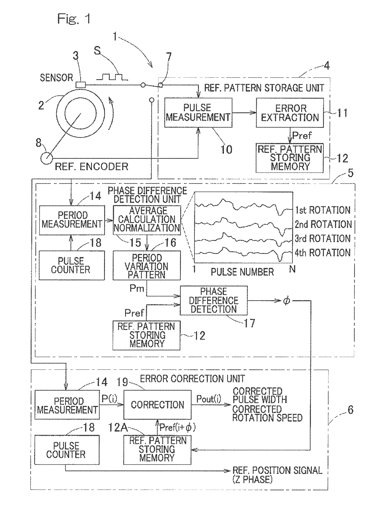
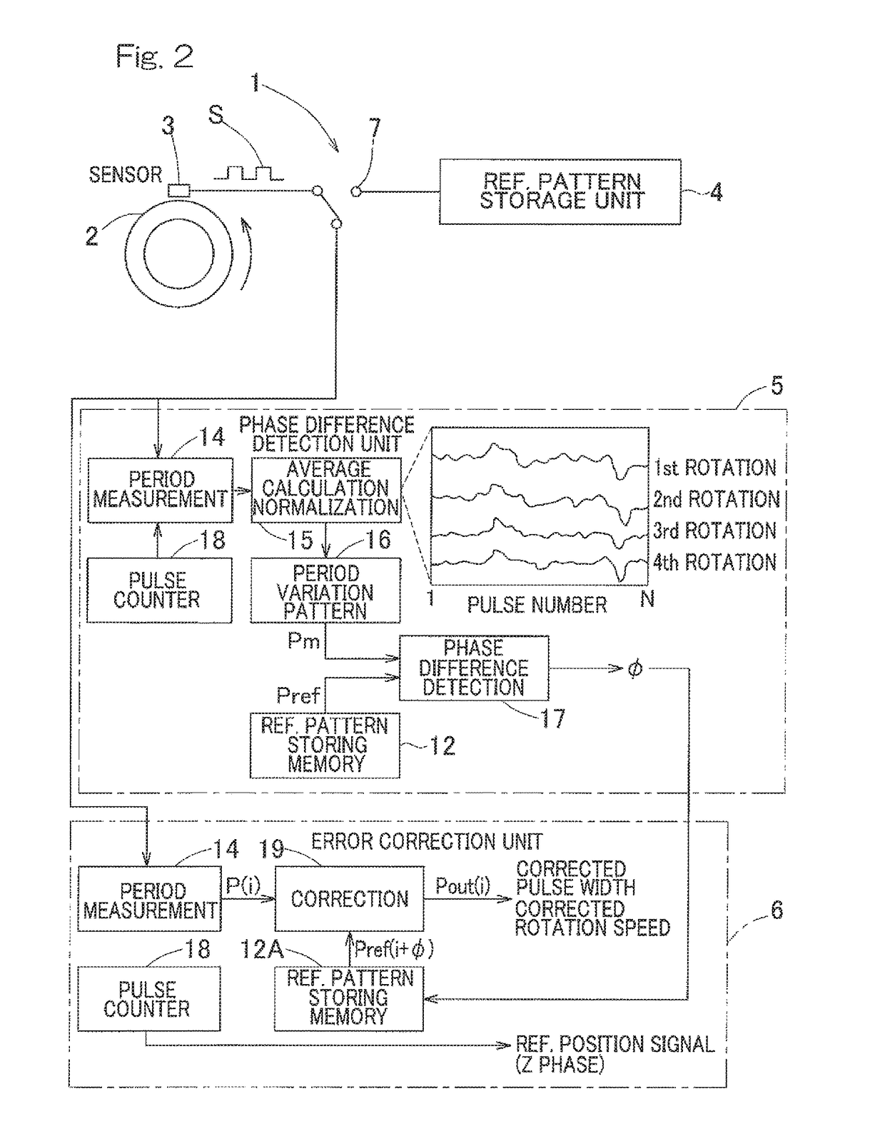
[0059]One embodiment of the present invention will be described with reference to the drawings. FIG. 1 is a block diagram showing a conceptual configuration of a rotation detection device according to this embodiment. This rotation detection device 1 includes: a ring-shaped encoder 2 rotatably provided and having a plurality of to-be-detected patterns cyclically arranged in the circumferential direction thereof; a sensor 3 which detects the to-be-detected patterns of the encoder 2 to generate a pulse signal S as a rotation signal; a reference pattern storage unit 4; a phase difference detection unit 5, and an error correction unit 6. The reference pattern storage unit 4 measures, during initial setting prior to operation, pitch errors corresponding to one rotation that are included in the to-be-detected patterns, and stores in advance the pitch errors as a reference pattern Pref. The phase difference detection unit 5 determines a pitch error pattern Pm corresponding to one rotation ...


PUM


Abstract

The rotation detection device includes: an encoder having to-be-detected patterns cyclically arranged in the circumferential direction; and a sensor configured to detect the to-be-detected patterns to generate pulses. The device further includes a reference pattern storage unit, a phase difference detection unit, and an error correction unit. The reference pattern storage unit measures pitch errors in the to-be-detected patterns prior to operation and stores the pitch errors as a reference pattern Pref. The phase difference detection unit determines a pitch error pattern Pm corresponding to one rotation of the to-be-detected patterns from rotation signals representing a plurality of rotations detected during operation, and performs comparison with a reference pattern Pref to determine a relative phase difference φ. Based on the phase difference φ obtained by the phase difference detection unit, the error correction unit corrects errors included in the rotation signals detected by the sensor.

Description

CROSS REFERENCE TO THE RELATED APPLICATION[0001]This application is a continuation application, under 35 U.S.C. §111(a), of international application No. PCT / JP2014 / 069536, filed Jul. 24, 2014, which claims priority to Japanese patent application No. 2013-155409, filed Jul. 26, 2013, the disclosure of which are incorporated by reference in their entirety into this application.BACKGROUND OF THE INVENTION[0002]Field of the Invention[0003]The present invention relates to a rotation detection device to be used in rotation angle detection and rotational speed detection in various types of apparatuses, and relates to a rotation detection device-equipped bearing unit having the rotation detection device incorporated therein.[0004]Description of Related Art[0005]As conventional examples of this type of rotation detection device, there have been presented speed detectors that have a function of correcting a duty ratio or a phase shift in an output signal of an encoder by use of a correction ...

Claims


Application Information

Patent Timeline
Patent Type & Authority Patents(United States)
IPC IPC(8): G01R33/025G01P3/481G01D5/244G01D5/14G01D5/249
CPCG01D5/2449G01D5/2448G01D5/249G01D5/145
Inventor TAKAHASHI, TORUNISHIKAWA, KENTARO
Owner NTN CORP
Features
  • R&D
  • Intellectual Property
  • Life Sciences
  • Materials
  • Tech Scout
  • Unparalleled Data Quality
  • Higher Quality Content
  • 60% Fewer Hallucinations
Learn More