Microwave assisted magnetic recording head with spin torque oscillator corner angle relationship, head gimbal assembly, and magnetic recording device

a technology of spin torque oscillator and magnetic recording head, which is applied in the direction of magnetic recording, data recording, instruments, etc., can solve the problems of less thermal stability of magnetic grains in association with their reduced volume, failure of recording on the magnetic recording medium, and increase in the anisotropic magnetic field (magnetic coercive force) of the magnetic recording medium. achieve the effect of sufficient assist

Active Publication Date: 2017-11-21
TDK CORPARATION
View PDF13 Cites 33 Cited by
  • Summary
  • Abstract
  • Description
  • Claims
  • Application Information

AI Technical Summary

Benefits of technology

[0009]The objective of the present invention is to provide a microwave assisted magnetic head, a head gimbal assembly, and a magnetic recording device having a spin torque oscillator capable of substantially evenly oscillating at a stable oscillation frequency, whereby a sufficient assist effect is obtained.
[0014]The present invention can provide a microwave assisted magnetic head, a head gimbal assembly, and a magnetic recording device having a spin torque oscillator capable of substantially evenly oscillating at a stable oscillation frequency, whereby a sufficient assist effect is obtained.

Problems solved by technology

However, a problem is that as the magnetic particles become smaller, the magnetic grains are less thermally stable in association with their reduced volume.
However, the increase in the Ku leads to an increase in the anisotropic magnetic field (magnetic coercive force) of the magnetic recording medium.
Therefore, if the anisotropic magnetic field of the magnetic recording medium exceeds an acceptable value determined based on the upper limit of the recording magnetic field intensity, recording on the magnetic recording medium fails.
As a result, the magnetic field intensity of the microwave magnetic field generated from the spin torque oscillator 10′ becomes lower, and thus sufficient assist effect cannot be obtained.

Method used


Image

  • Microwave assisted magnetic recording head with spin torque oscillator corner angle relationship, head gimbal assembly, and magnetic recording device
  • Microwave assisted magnetic recording head with spin torque oscillator corner angle relationship, head gimbal assembly, and magnetic recording device
  • Microwave assisted magnetic recording head with spin torque oscillator corner angle relationship, head gimbal assembly, and magnetic recording device

Examples


experimental example 1

[0077]Using an analysis model of the microwave assisted magnetic head 1 having the configuration shown in FIGS. 4, 5A, and 5B, the ratio of the average in-plane magnetization value of the magnetic field generation layer 14 to the saturation magnetization of the magnetic field generation layer 14 of the spin torque oscillator 10 (the in-plane magnetization rate RM) was obtained by simulation. The simulation analysis experiment was conducted using the three dimensional finite-element-boundary-integral (FEBI) method, which is an electromagnetic field analysis.

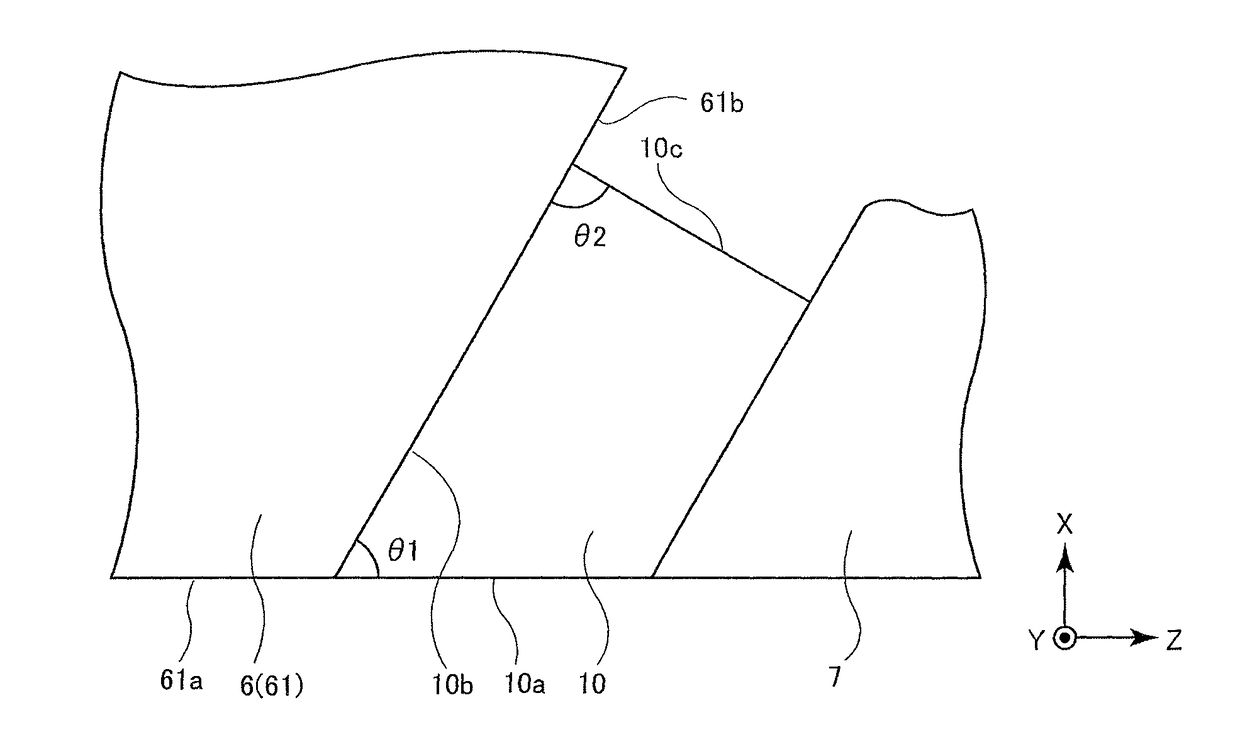
[0078]As the microwave assisted magnetic head 1, a model in which the main magnetic pole layer 6 (main magnetic pole part 61) consisted of CoFeNi and had a saturation magnetic flux density (Bs) of 2.4 T, and the trailing shield 7 consisted of CoFeNi or a material having the same material characteristic as the main magnetic pole layer 6 (main magnetic pole part 61) was adopted. As the spin torque oscillator 10 in the model, the spi...


PUM

PropertyMeasurementUnit
non-orthogonal angleaaaaaaaaaa
angle θ2aaaaaaaaaa
angle θ1aaaaaaaaaa

Abstract

A microwave assisted magnetic head includes a main magnetic pole; a trailing shield; and a spin torque oscillator provided between the main magnetic pole and the trailing shield. The spin torque oscillator has a first end surface configuring a part of an air bearing surface, a second end surface facing the main magnetic pole, and a third end surface facing the first end surface, the first angle θ1 made by the first end surface and the second end surface is smaller than the second angle θ2 formed by the second end surface and the third end surface, and the second angle θ2 is 80 to 100 degrees.

Description

FIELD OF THE INVENTION[0001]The present invention relates to a microwave assisted magnetic head, a head gimbal assembly, and a magnetic recording device.BACKGROUND OF THE INVENTION[0002]In the field of magnetic recording using a head and a medium, further improvement in performance of the magnetic recording medium and the magnetic head is demanded as the magnetic disc device has higher recording densities.[0003]A magnetic recording medium is a discontinuous medium consisting of a set of magnetic grains, and each magnetic grain has a single-domain structure. In the magnetic recording medium, one recording bit consists of a plurality of magnetic grains. Therefore, in order to increase the recording density, the magnetic grains must be smaller, and the borders between adjacent recording bits must be less uneven. However, a problem is that as the magnetic particles become smaller, the magnetic grains are less thermally stable in association with their reduced volume.[0004]A presumable m...

Claims


Application Information

Patent Timeline
Patent Type & Authority Patents(United States)
IPC IPC(8): G11B5/31G11B5/127G11B5/235G11B5/00
CPCG11B5/1278G11B5/235G11B5/3146G11B5/314G11B2005/0024G11B5/3116
Inventor TANG, ZHENYAOROPPONGI, TETSUYASOENO, YOSHIKAZUMATSUZAWA, HIRONOBUTAKAHASHI, HIROKAZU
Owner TDK CORPARATION
Why Eureka
Try Eureka