
Integration of quantitative calibration systems in computed tomography scanners

a computed tomography and calibration system technology, applied in tomography, diagnostics, applications, etc., can solve the problems of conventional challenge to metrics, fragility fractures, and increasing health burden of osteoporosis

Active Publication Date: 2017-11-28
THE JOHN HOPKINS UNIV SCHOOL OF MEDICINE
View PDF8 Cites 4 Cited by
  • Summary
  • Abstract
  • Description
  • Claims
  • Application Information

AI Technical Summary

Benefits of technology

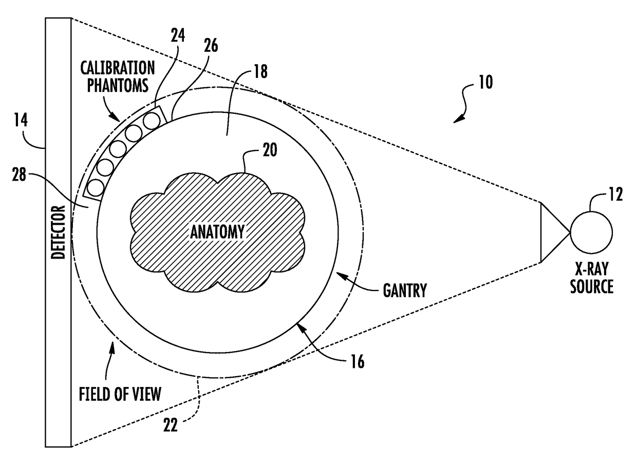
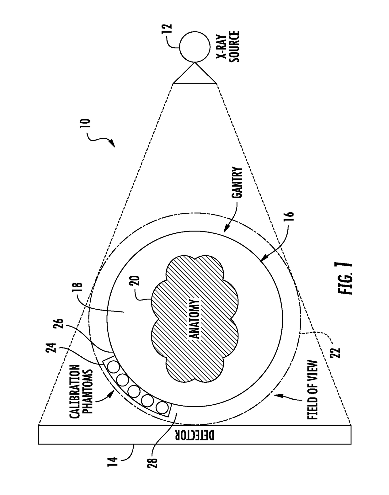
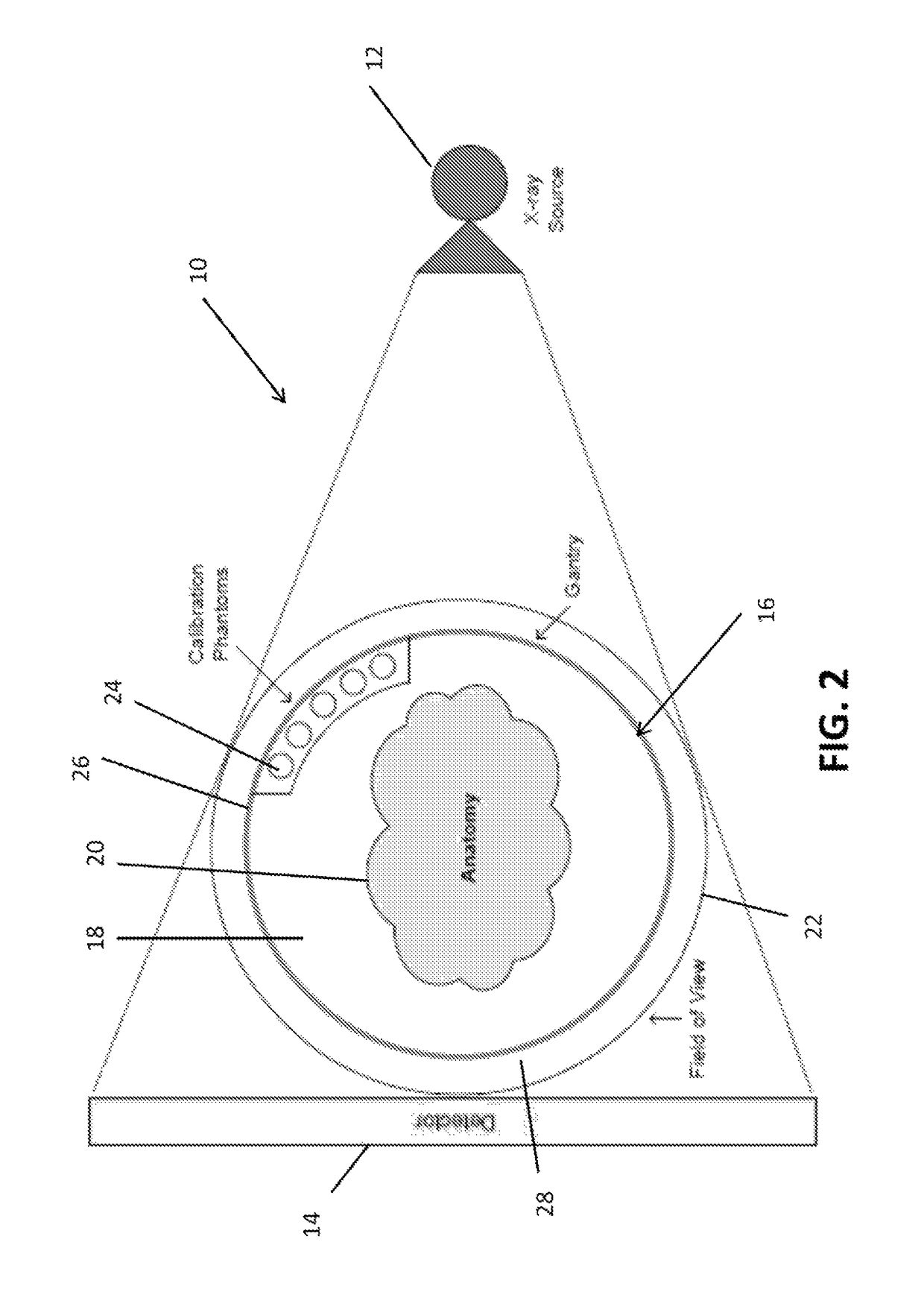
The present invention is a device for calibrated computed tomography (CT) scanning and calibration phantoms integrated within the scanner gantry. The calibration phantoms are used for accurate calibration of the scanner for measurement of bone mineral density (BMD) and can be positioned within the gantry. The device can also include a calibration phantom in the form of five or six cylindrical calibration phantoms that are placed longitudinally in a ring around the gantry opening and are spaced to ensure that they are all within the field of view. The calibration phantoms are of known dimensions and composed of materials of known Hounsfield unit (HU) and calcium density. The device can be used for weight bearing imaging. Overall, the invention aims to improve the accuracy and reliability of CT scanning for BMD measurement.

Problems solved by technology

For example, osteoporosis presents a growing health burden involving reduction in bone density leading to fragility fractures.
Such metrics have been conventionally challenged because of the limited spatial resolution of clinical (whole-body) CT scanners and have therefore been less frequently utilized.
However it is only able to measure areal densities.
However, variability in phantom location can cause degradation in BMD accuracy, and positioning of the phantoms can affect overall workflow, total scan time, and patient comfort.
Also, variability in phantom location requires user interaction in localizing them during BMD calculations and can affect the accuracy of BMD estimates.
As a result, densitometry information can only be derived from the CT scan if an additional calibration phantom is introduced at the time of the scan or, perhaps, if a separate scan is required for quantitative imaging purposes.

Method used


Image

  • Integration of quantitative calibration systems in computed tomography scanners
  • Integration of quantitative calibration systems in computed tomography scanners
  • Integration of quantitative calibration systems in computed tomography scanners

Examples


Embodiment Construction

[0029]The presently disclosed subject matter now will be described more fully hereinafter with reference to the accompanying Drawings, in which some, but not all embodiments of the inventions are shown. Like numbers refer to like elements throughout. The presently disclosed subject matter may be embodied in many different forms and should not be construed as limited to the embodiments set forth herein; rather, these embodiments are provided so that this disclosure will satisfy applicable legal requirements. Indeed, many modifications and other embodiments of the presently disclosed subject matter set forth herein will come to mind to one skilled in the art to which the presently disclosed subject matter pertains having the benefit of the teachings presented in the foregoing descriptions and the associated Drawings. Therefore, it is to be understood that the presently disclosed subject matter is not to be limited to the specific embodiments disclosed and that modifications and other ...


PUM


Abstract

An embodiment in accordance with the present invention provides a device and method for a quantitatively calibrated computed tomography scanner. The device includes a gantry configured for receiving a patient or part of a patient. The gantry includes an X-ray source and a detector positioned opposite said X-ray source, such that said detector receives the X-rays emitted from the X-ray source. Calibration phantoms are integrated with the gantry and / or a device within the scanner so as to allow for calibration in quantitative CT measurements of Hounsfield units and / or bone mineral density.

Description

CROSS REFERENCE TO RELATED APPLICATIONS[0001]This is a national stage application under 35 U.S.C. §371 of PCT / US2013 / 044673 filed Jun. 7, 2013, the entire contents of which are incorporated herein by reference and this application claims the benefit of U.S. Provisional Application No. 61 / 656,775 filed on Jun. 7, 2012, which is incorporated by reference, herein, in its entirety.FIELD OF THE INVENTION[0002]The present invention relates generally to medical imaging. More particularly, the present invention relates to a device for determining bone mineral density in computed tomography (CT).BACKGROUND OF THE INVENTION[0003]Diagnosis and treatment of a spectrum of musculoskeletal diseases stand to benefit from high-quality, accurate imaging and morphological assessment as provided by peripheral quantitative CT (pQCT). For example, osteoporosis presents a growing health burden involving reduction in bone density leading to fragility fractures. Similarly, and particularly in an aging and o...

Claims


Application Information

Patent Timeline
Patent Type & Authority Patents(United States)
IPC IPC(8): A61B6/00A61B6/03
CPCA61B6/583A61B6/032A61B6/5217A61B6/505A61B6/508A61B6/4085G16H50/30
Inventor SIEWERDSEN, JEFFREY H.AL MUHIT, ABDULLAHCARRINO, JOHN
Owner THE JOHN HOPKINS UNIV SCHOOL OF MEDICINE
Learn More